7 Pin Trailer Wiring Diagram Australia Printable Form, Templates and Letter
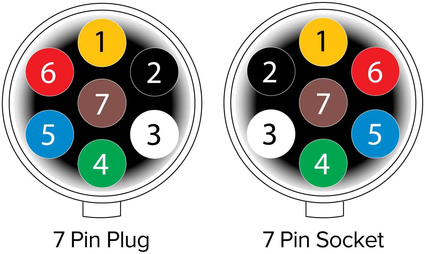
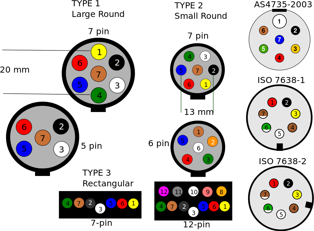
7 Pin Flat Plug and Socket. Flat connectors comply with Australian Standard AS4177.5-2004. Narva 7 & 12 Pin trailer connectors comply with all relevant ADRs. A colour coded trailer plug wiring guide to help you require your plugs and sockets. Includes guides for 7 pin, 6pin, 5 pin, 12 pin, 13 pin, pin and heavy duty round plugs and sockets.
7 Pin Rv Wiring / 7 Pin Trailer Connector Wiring Diagram World The first component is
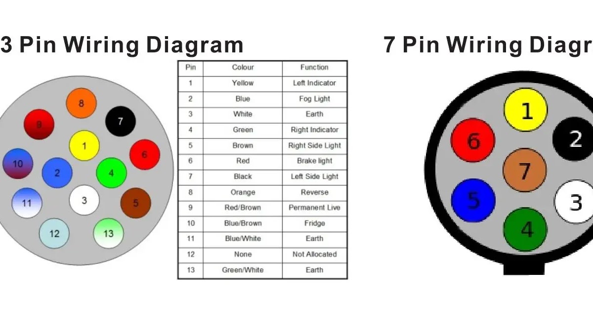
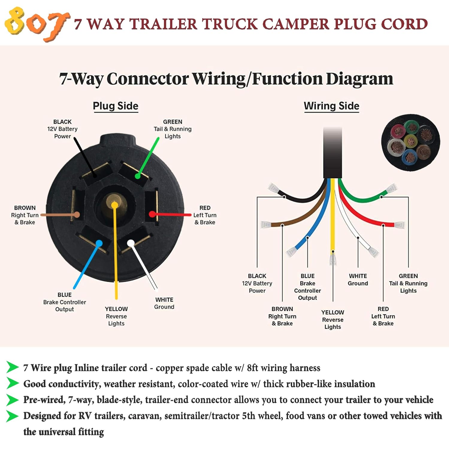
The 7 pin trailer wiring diagram for each trailer type (standard, RV, heavy duty) Descriptions and illustrations of where and how to properly connect all wiring Table of Contents show 7 Pin Trailer Wiring - Color Codes There are seven different electrical wires that connect and sync the 7 pin trailer connector with your vehicle.

Wiring Diagram For 7 Prong Trailer Plug Trailer Wiring Diagram
It usually comes in round pin configurations. 7-pin plug utilizes seven distinct metal pin contacts to transfer electricity and signals for operating trailer lighting, electric brakes, backup lights, a 12V power supply, and other needs.
7 Pin Trailer Plug Wiring Diagram Flat Wiring Diagram
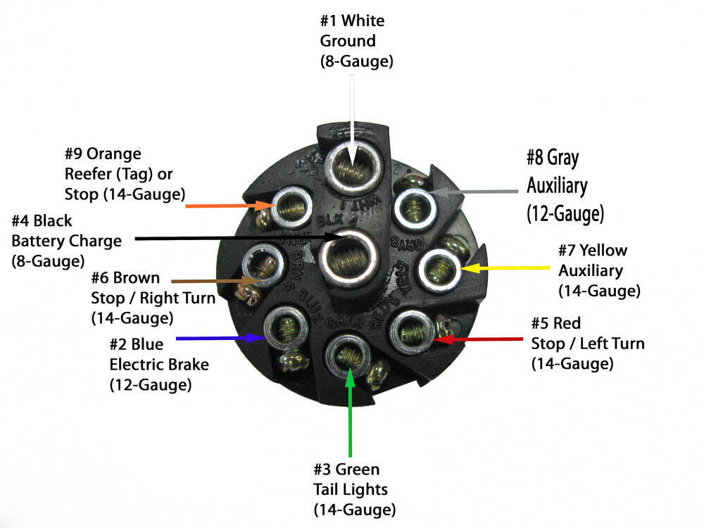
Wiring Diagram for 7-Way Round Pin Trailer and Vehicle Side Connectors Question: wiring pollak j560jun93 to 7pin round narva truck to trailer thank. asked by: Michael Expert Reply: I have added a photo detailing the wiring connections for the Pollack Heavy-Duty, 7-Pole, Round Pin conncetor, # PK11700, see link.
Standard 7 Pin Trailer Plug Wiring Diagram
Various connectors are available from four to seven pins that allow for the transfer of power for the lighting as well as auxiliary functions such as an electric trailer brake controller, backup lights, or a 12V power supply for a winch or interior trailer lights.

Understanding 7 Pin Trailer Plug Wiring Diagram Usa Wiring Diagram
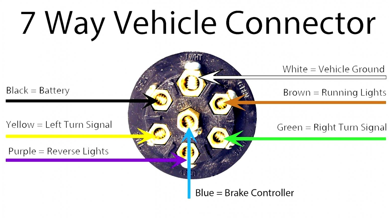
Pin 1: Auxiliary or Reverse Lights Pin 2: Brake Lights Pin 3: Right Turn Signal Pin 4: Left Turn Signal Pin 5: Ground Pin 6: Electric Brakes Pin 7: Battery/Charging Wiring Diagram for a 7-Pin Plug Once you understand the purpose of each wire in the 7-pin plug, you can create a wiring diagram to ensure the correct connections are made.

Seven Pin Trailer Wiring Diagram
How to connect a trailer plug if you don't know the wire colorsHow to wire a 7 pin trailer plug (diagram shown)How to wire a trailer plug - 7 pin (diagrams s.
Wiring Diagram 7 Pin Trailer Connector
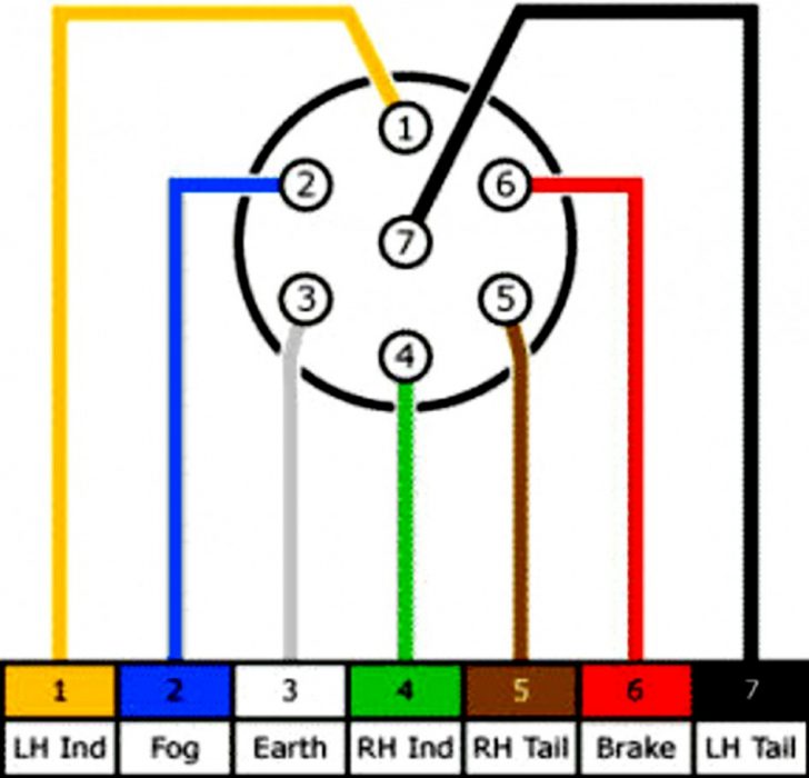
The 7 pin round trailer plug diagram is divided into two sections: the power side and the ground side. On the power side, there are five terminals that provide the power for the trailer. These include left turn signal, right turn signal, running lights, brake lights, and ground. The ground side has two terminals for the trailer brakes and a.
7 Pin Connector Wiring Diagram
The 7-Way Trailer Plug is around 2″ diameter connector that allows an additional pin for an auxiliary 12-volt power or backup lights. It is usually used for towing heavy-duty cargo trailers, aluminum trailers, dump trailers, utility / landscape trailers, equipment trailers, open car haulers and enclosed car haulers.
7 Pin Trailer Plug Wiring Diagram Wiring Diagram
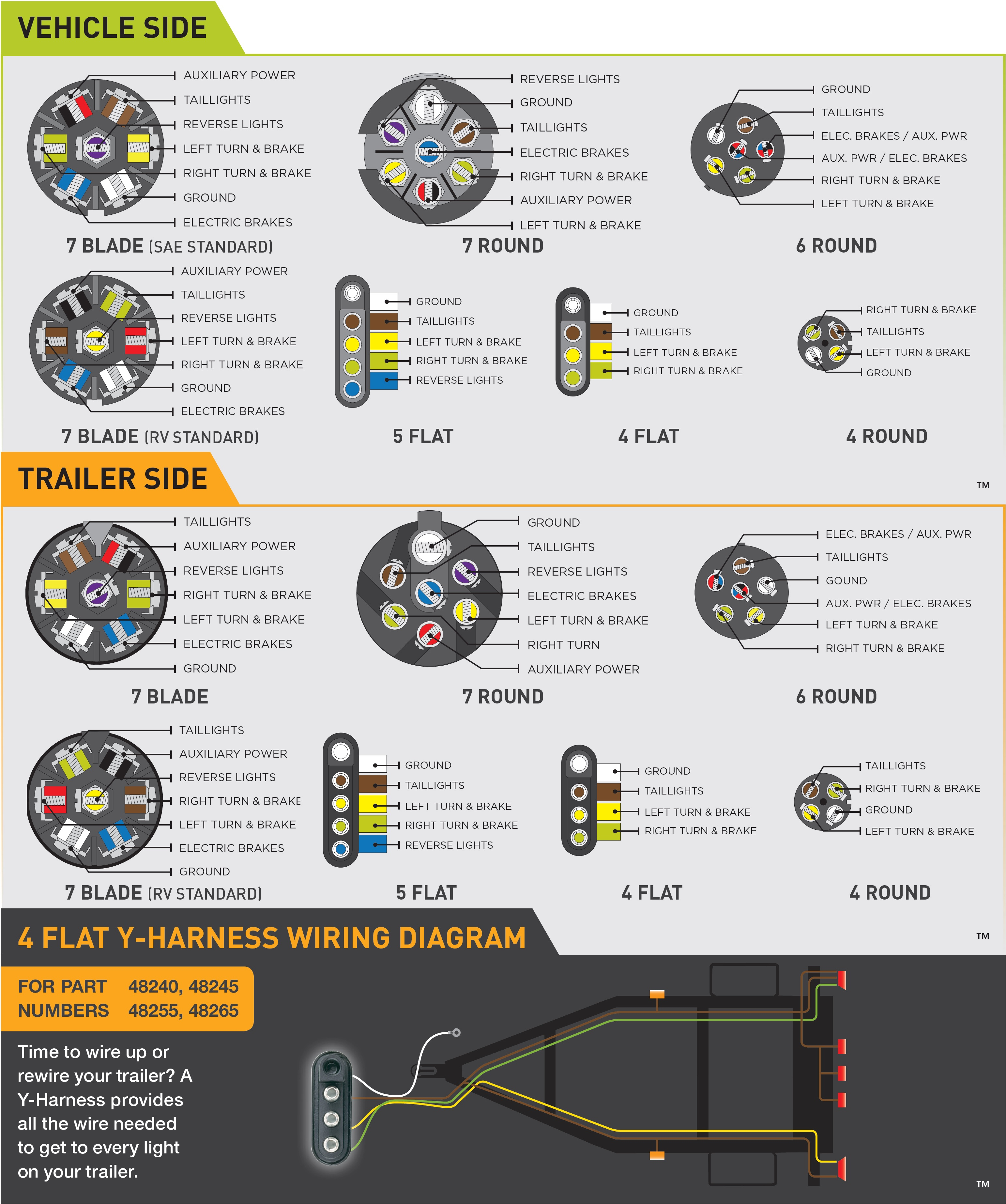
Understanding Towing Trailer Wiring Diagram and Installation Help - Chapter 7 Trailer Wiring Diagram and Installation Help Chapter 7 Equipping Your Vehicle with Proper Trailer Wiring Any vehicle towing a trailer requires a trailer wiring harness to safely connect the taillights, turn signals, brake lights and other necessary electrical systems.

Seven Pin Wiring Schematic
The 7 pin round trailer wiring diagram shows a connection between the trailer plug and the trailer wiring. This diagram usually comes with the trailer. It is the most common type of connection used for trailers. The diagram shows the color-coded wires that are used to connect the trailer plug to the trailer wiring. The 7 pin connector consists.
Trailer Wiring Diagram 7 Pin Wiring Diagram
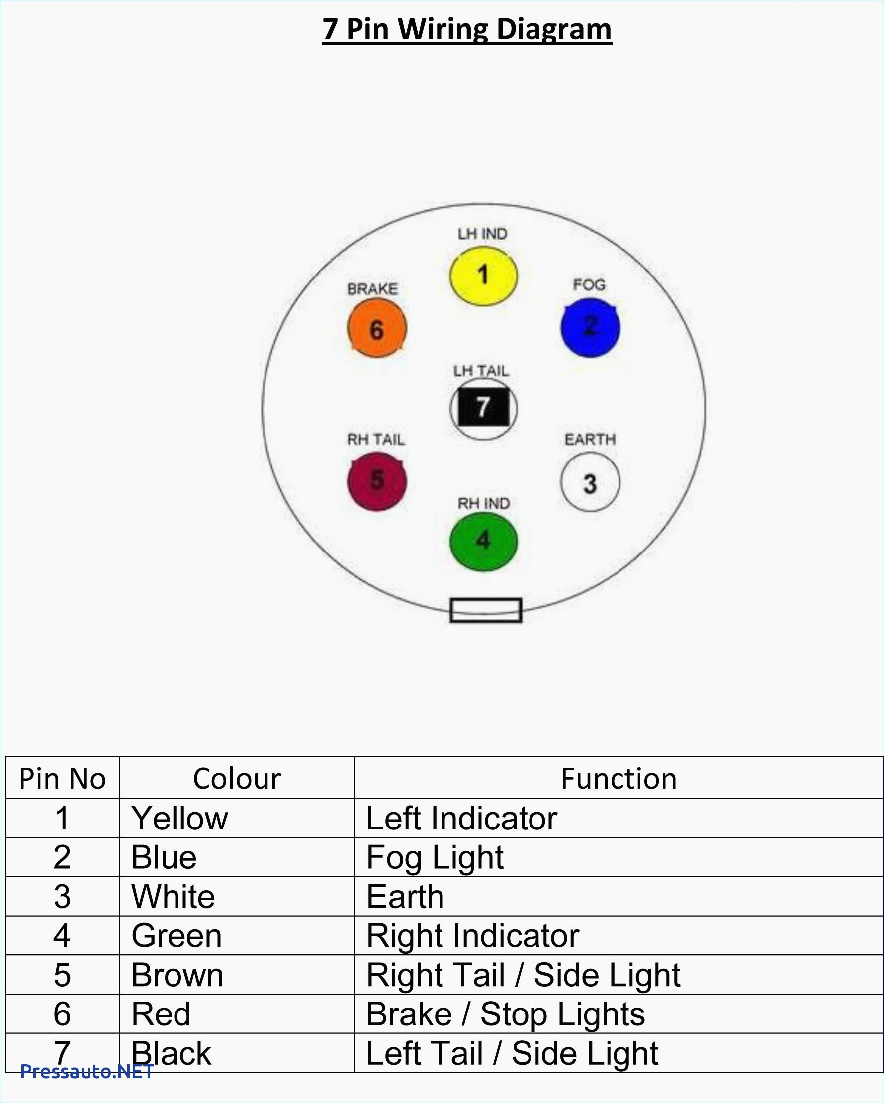
A 7 pin trailer wiring diagram is a schematic that shows the pinout and function of each wire in a 7-way round trailer connector. The standard 7-pin connector contains the following wires and functions: The diagram uses color coding and labeling to identify the purpose of each pin's wire. It traces the path of the wires from the connector.
7 Pin Plug Wiring / Trailer Wiring Diagrams North Texas Trailers Fort Worth 11/10 for 2011
A wiring diagram for a 7-pin plug is a detailed illustration showing the electrical connections and circuitry of a 7-pin plug, which is commonly used for trailers and towing vehicles. This diagram provides a clear visual representation of how to connect the different wires and pins of the plug, ensuring proper functionality and safety. It is a valuable resource for individuals who need to.

Wiring Diagram For Trailer 7 Pin Plug Wiring Diagram Schemas
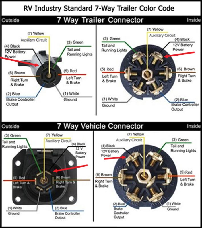
7 Way Plug Wiring Diagram Standard Wiring* This is the most common (Standard) wiring scheme for RV Plugs and the one used by major auto manufacturers today. * Always test wires for function and wire accordingly. This wiring scheme is for reference only. copyright © 2001, Country Trailer Sales All Rights Reserved
7 Pin Trailer Connector Wiring Diagram World
Step 1: Gather the necessary tools and materials Before you begin, make sure you have all the tools and materials required for the installation. This includes a 7 pin trailer plug, wire strippers, electrical tape, a wire cutter, and a screwdriver. It's also a good idea to have a wiring diagram or guide specific to your trailer plug model.
Wire Schematic For 7 Pin Trailer
Step 1: Gather the necessary tools and materials Before you begin wiring a 7-pin trailer connector for your Chevrolet, it is important to gather all the necessary tools and materials. This will ensure that you have everything you need to complete the installation process smoothly and efficiently. Here are some tools and materials you will need: