
PIN OUT NODEMCU DAN INSTALASI BOARD NODEMCU KE ARDUINO IDE SINAU
THE 15 BEST Things to Do in Community of Madrid - 2024 (with Photos) - Tripadvisor. Things to do near Home Club Torre Madrid. Expert Tour of Madrid in Private Eco Tuk Tuk. per adult (price varies by group size) Things to Do in Community of Madrid, Spain: See Tripadvisor's 3,156,780 traveler reviews and photos of Community of Madrid tourist.
NodeMCU board V1 Control LED (internal) tutorial Secure Instrument
The ESP8266 NodeMCU is equipped with a total of 17 GPIO pins, conveniently placed on the pin headers on both sides of the development board. These pins can be assigned various peripheral tasks, offering flexibility in their usage.
ESP8266 NodeMCU Tutorial
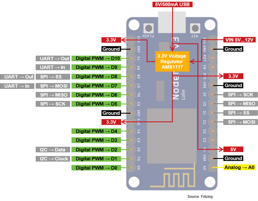
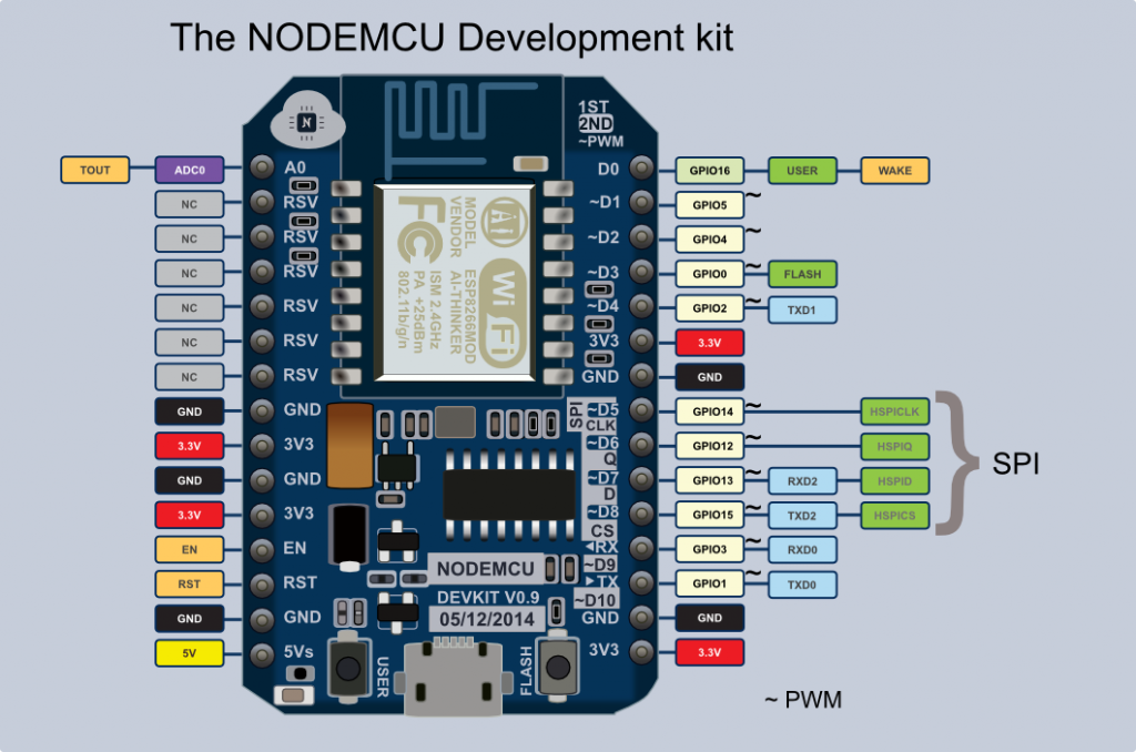
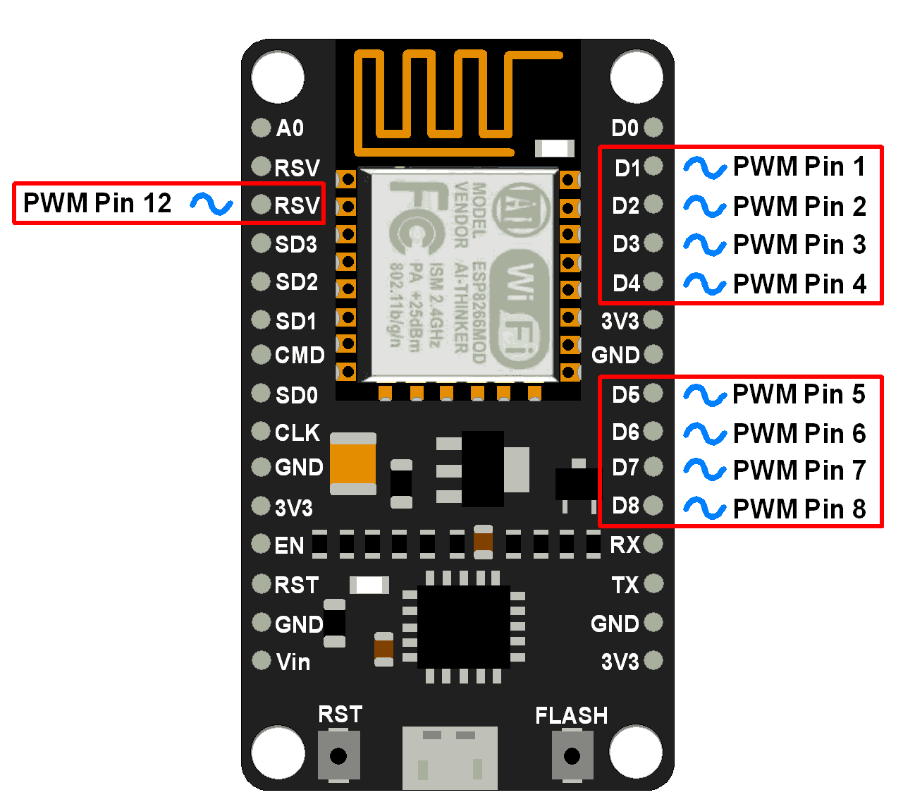
NodeMCU esp8266 wifi module is an open-source, low-cost, low-power MCU (microcontroller unit) development board. It has 17 GPIO pins (11 are Digital I/O pins), out of which one pin is an analog pin, 4 pins support PWM, 2 pairs are for UART (UART0 and UART1), and supports 1x SPI and 1x I2C protocol. NodeMCU ESP8266 has 128Kb of Ram, 4 MB of.
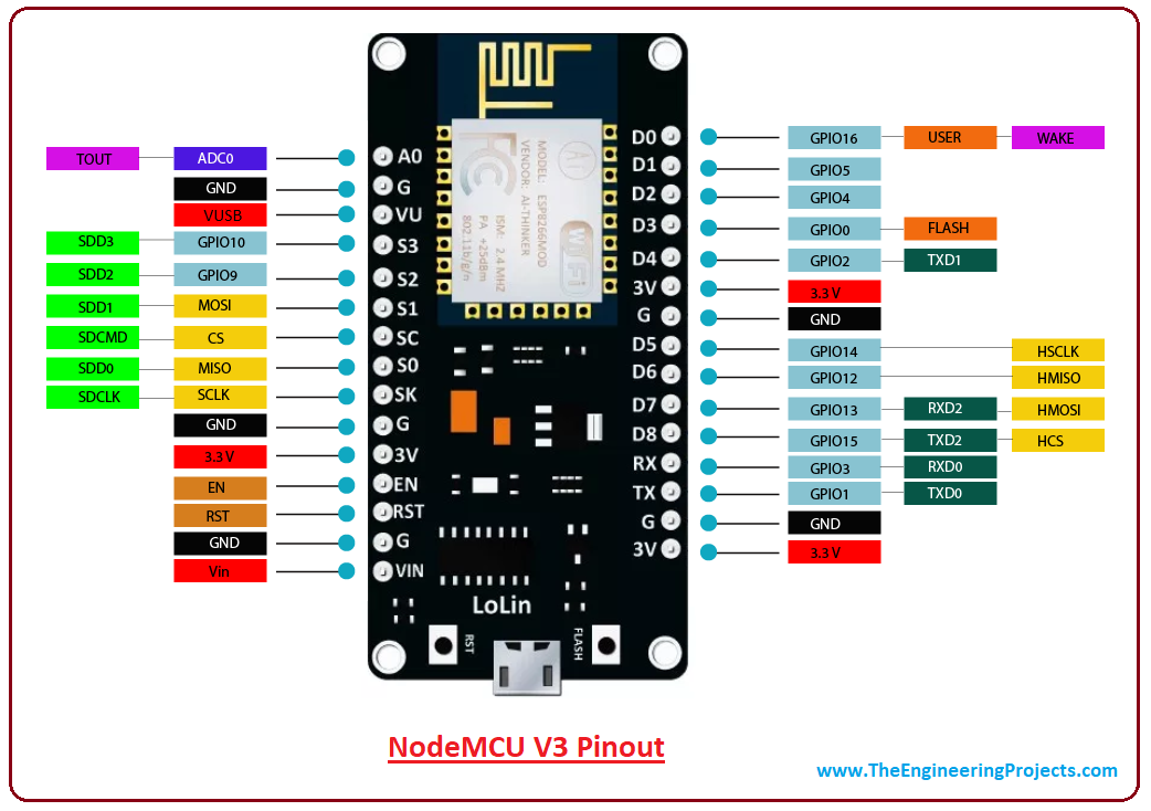
Introduction to NodeMCU V3 The Engineering Projects
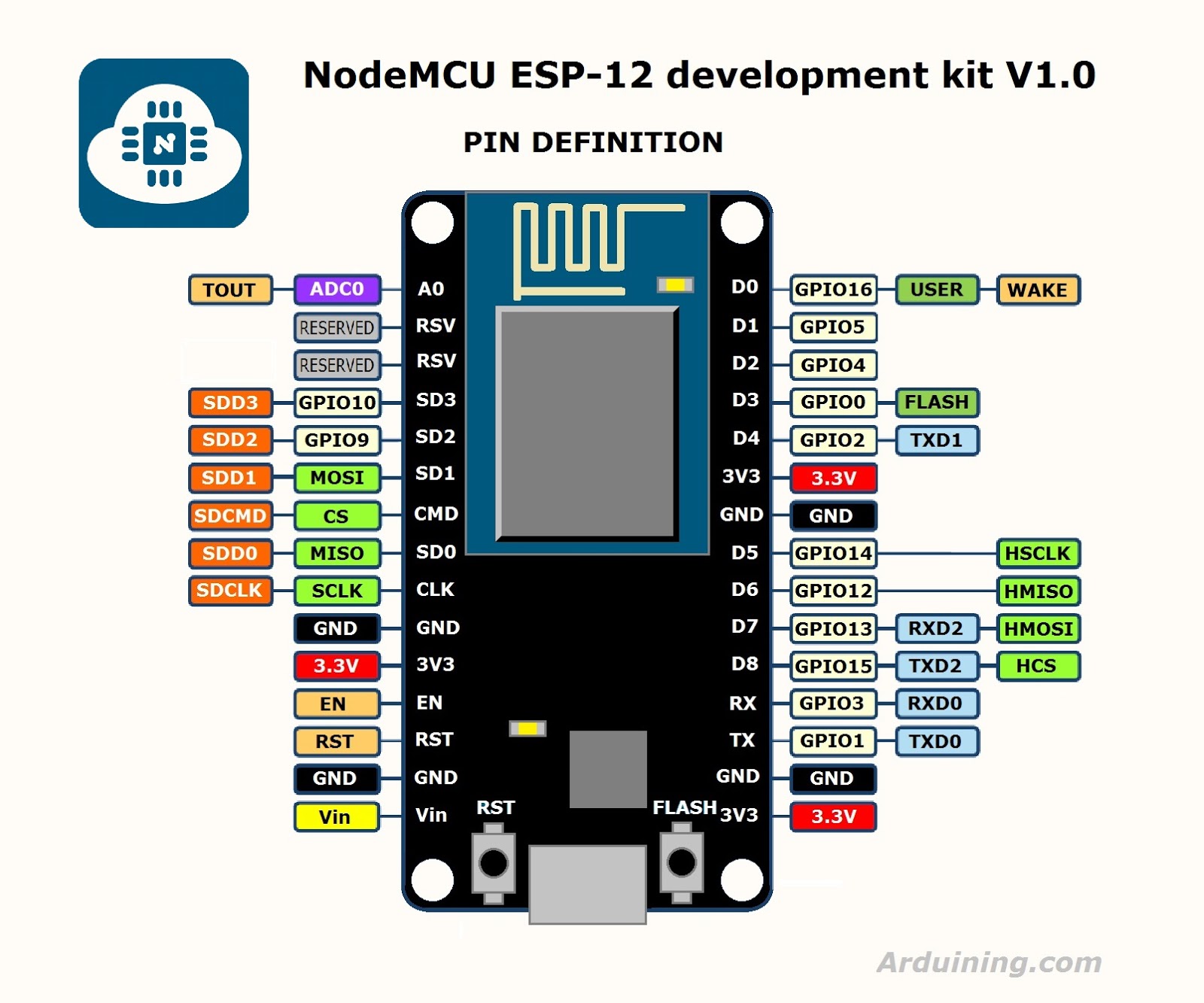
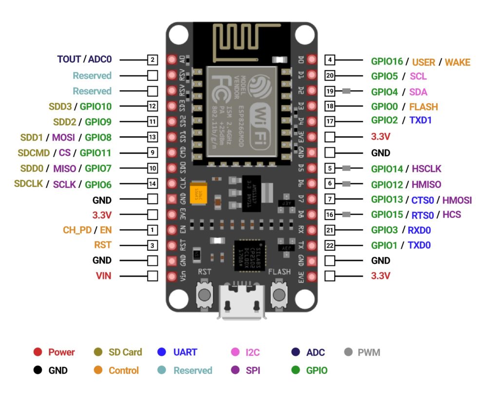
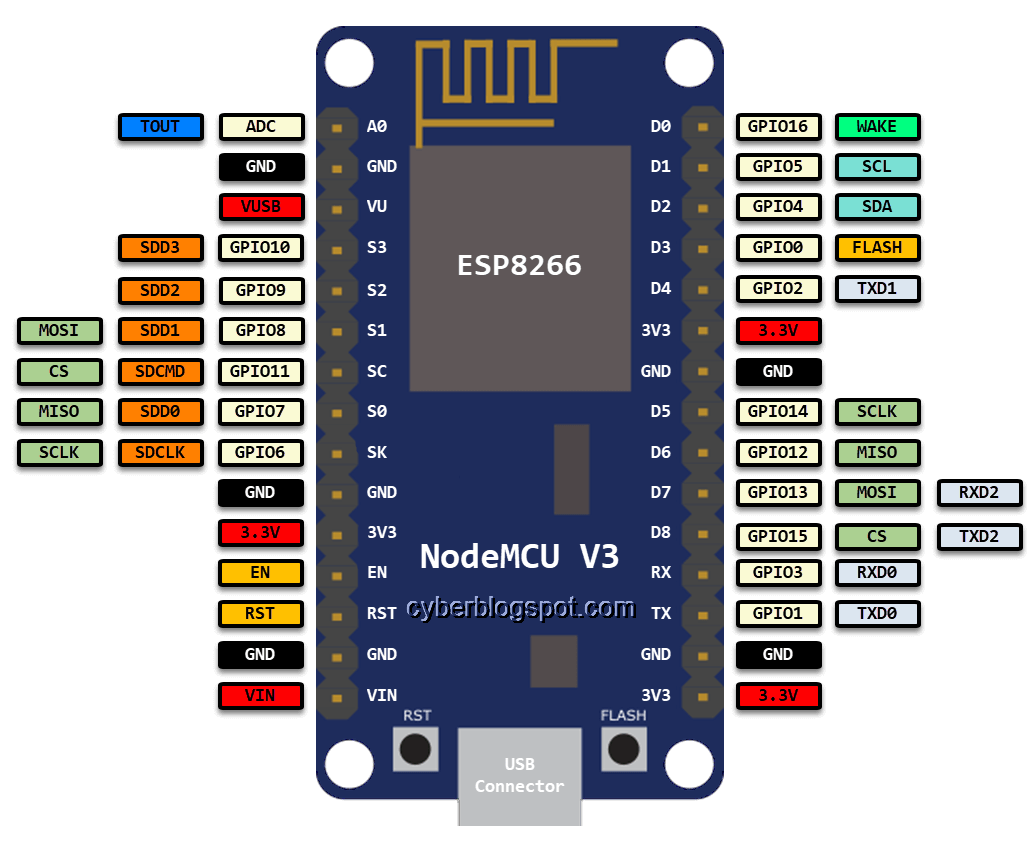
NodeMCU Pinout The following image shows the pinout for NodeMCU board. A typical NodeMCU board (if it is based on the original NodeMCU Devkit design) has 30 pins. In this, 8 pins are related to power and 2 are reserved.

Introduction to NodeMCU Phipps Electronics
In this tutorial, we will see the Pinouts of both NodeMCU board as well as the ESP-12E Module, which is the base board for NodeMCU. The ESP12-E Pinout will be helpful if you are developing your own hardware and understanding the NodeMCU Pinout is very useful if you are working with ESP8266 NodeMCU board. Outline Introduction
"Nodemcu V3 Pinout" Tutorials
NodeMCU Pinout While ESP-01 is the bare minimum ESP8266 Module, the NodeMCU is a popular compressive solution. It is a proper ESP8266 Development board with all the necessary connectors and components. NodeMCU uses ESP-12E Module, again by Ai-Thinker. This module, like the ESP-01, has the SoC, Crystal Oscillator, and Wi-Fi Antenna.
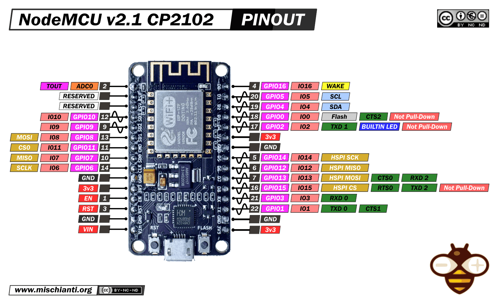
NodeMCU v2 and v2.1 high resolution pinout and specs Renzo Mischianti
11 digital pins (D0 to D10) are available on NodeMCU and can be used for input and output activities. These pins can accommodate digital signals with 3.3V voltage levels. UART Pins Two UART (Universal Asynchronous Receiver-Transmitter) pins, marked TX and RX, are available on the NodeMCU board.
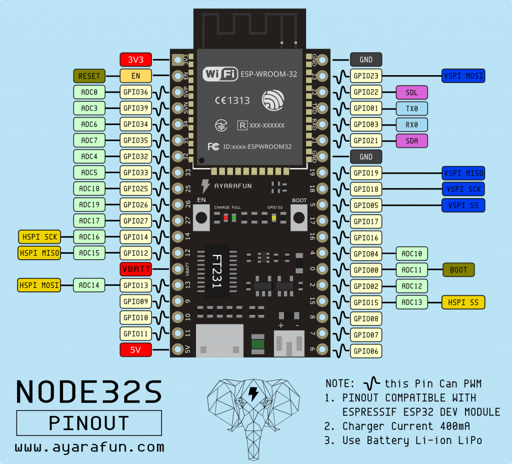
"Nodemcu Esp32 Pinout" Tutorials
This article helps you to understand the Nodemcu Pinout, how to use that and you will also learn what are pins used to read digital inputs like a button switch and control digital outputs like an LED using a nodemcu board with Arduino IDE. ESP8266 Nodemcu is a microcontroller board with built-in wifi. NodeMCU comes with an Esp8266 12-E chip comes.
The beginner guide and getting started with nodemcu
Analog Input Pins (ADC): 1. 2 UARTs 4 SPIs 1 I2C 4 MB memory (flash) 64 KB SRAM The adjustable clock speed of 80 - 160 MHz
ESP8266 12E NodeMCU kit pinout diagram Nick Agas
Step 1: NodeMCU Devkit 1.0 The term NodeMCU usually refers to the firmware, while the board is called Devkit. NodeMCU Devkit 1.0 consists of an ESP-12E on a board, which facilitates its use. It also has a voltage regulator, a USB interface. Ask Question Comment Step 2: ESP-12E
NodeMCU ESP8266 Vs. Arduino UNO Board
The NodeMCU interferes just a little with ESP-12 pins. It does an untreated exposure of each of them. It is interesting to see what NodeMCU adds or changes to the ESP-12. Power Source ESP8266 operates on 3.3V, ESP-12 exposes the VDC pin for direct power.
CyberBlogSpot
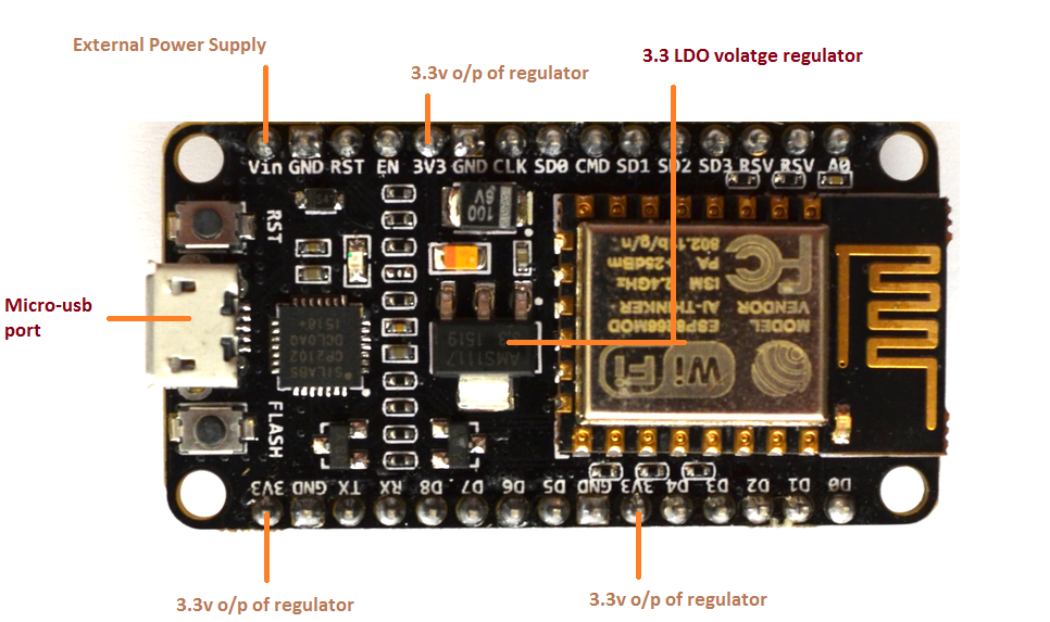
NodeMCU can be powered using a Micro USB jack and VIN pin (External Supply Pin). It supports UART, SPI, and I2C interface. Programming NodeMCU ESP8266 with Arduino IDE The NodeMCU Development Board can be easily programmed with Arduino IDE since it is easy to use. Programming NodeMCU with the Arduino IDE will hardly take 5-10 minutes.
Getting Started with NodeMCU Board Powered by ESP8266 WiSoC CNX Software
The ESP8266 12-E NodeMCU kit pinout diagram is shown below. Wemos D1 Mini Pinout The following figure shows the WeMos D1 Mini pinout. Download PDF with ESP8266 Pinout Diagrams We've put together a handy PDF that you can download and print, so you always have the ESP8266 diagrams next to you: Download PDF Pinout Diagrams » ESP8266 Peripherals

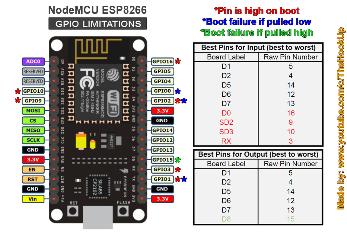
How To Pick the right input/output pins on the ESP8266 and ESP32 based
The ESP8266 NodeMCU has 17 GPIO pins in total, which are broken out to the pin headers on both sides of the development board. These pins can be assigned a variety of peripheral duties, including: 1 ADC channel: 1 channel of 10-bit precision SAR ADC: 2 UART interfaces:
Nodemcu ESP8266 Pinout, Features, and specifications
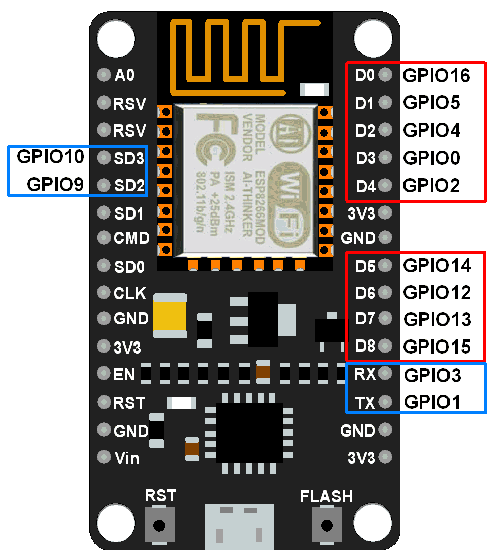
As for the GPIO pins on the NodeMCU ESP8266 board, it should be noted that only the pin A0 is available as an analog input from the pins on the left side of the board (when you hold the board in a way that the USB port is at the bottom and the antenna is at the top). GPIO6 to GPIO11, which are on the same side, are not intended for external use.
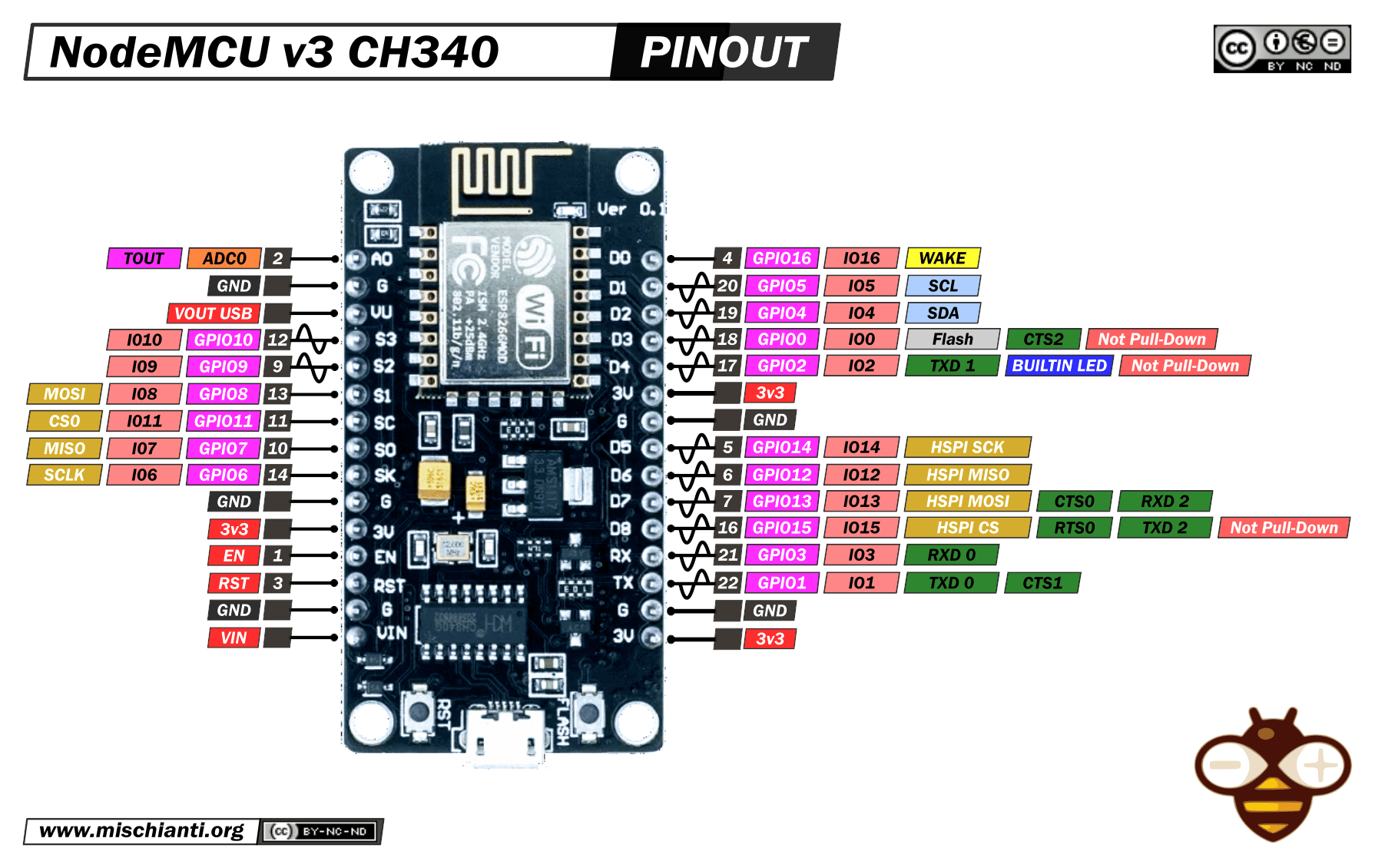
NodeMCU v3 high resolution pinout and specs Renzo Mischianti
If you looked at the ESP8266 NodeMCU Pinout, you will realize that not all the GPIO Pins of the NodeMCU Board can be used as simple GPIO Pins foe Digital Input and Output operations. Out of the 17 GPIO Pins, 8 are already used for other operations like UART, SPI Flash. So, you are left with 9 GPIO Pins.