Single Phase Forward Reverse Switch Wiring Diagram
a. Circuit diagram. The figure below is a basic control circuit diagram for reversing a three-phase motor using a three-position switch. Basic reverse forward control circuit diagram. b. Working principle: + When the main contact of KF contactor is closed, the motor runs in the forward direction. Conversely, when the main contact of KR.
How To Wire Single Phase Forward Reverse Swith / Need help setting up
The exact wiring diagram will vary depending on the specific VFD model and motor type, so it is important to refer to the manufacturer's instructions for the specific wiring details. Step 2: Control Wiring. Once the motor is connected to the VFD, the next step is to wire the control circuit for forward and reverse operation.
Forward Reverse Motor Control Diagram For 3 Phase Motor Electrical
A forward reverse wiring diagram is a schematic representation of the electrical connections within a circuit that controls the forward and reverse motion of a motor or any other electrical device. This diagram is essential in understanding and troubleshooting the circuit, as it provides a visual representation of how the components are.
forward reverse wiring diagram for single phase motor Wiring Diagram
The Ezgo forward reverse switch is an essential component of the golf cart's electrical system. It allows the cart to move forward or reverse direction, depending on the desired movement. Understanding the wiring of this switch is crucial for troubleshooting and repairing any issues that may arise.

How To Wire Single Phase Forward Reverse Swith Help Wiring GE motor
Developing a Wiring Diagram The same basic procedure is used to develop a wiring diagram from the schematic as was followed in the previous chapters. The components needed to construct this circuit are shown in Figure 29-10. In this example, assume that two contactors and a separate three-phase overload relay are to be used. The

Forward Reverse Circuit Diagram
There are two main types of DC motor forward-reverse switch wiring diagrams: single-pole and double-pole. A single-pole diagram is used when there is only one power source and one set of wires that need to be connected. This type of diagram is often used in simple electronics projects.

DC motor two way switch reverse forward wiring with direction indicator
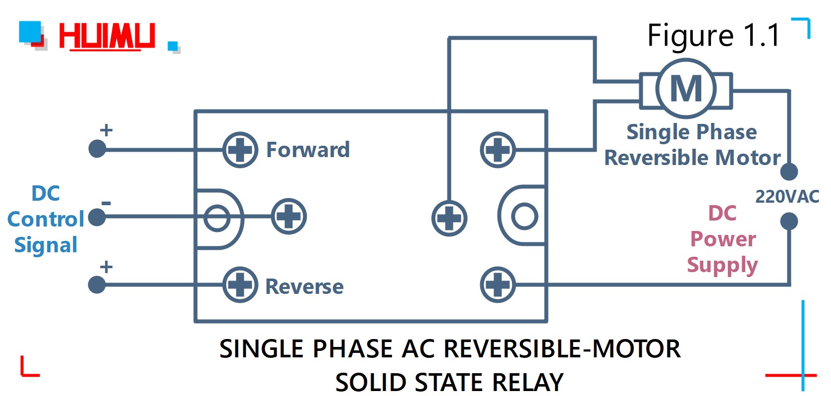
A forward reverse contactor is a device that allows for the reversal of current flow in a single phase motor. This device works by switching between two states, either forward or reverse. When in the forward state, the motor will rotate clockwise, whereas when it's in the reverse state, it will rotate counter-clockwise.

How To Wire Single Phase Forward Reverse Swith 301 Moved Permanently
The forward reverse switch is an essential component in electrical circuits that control the direction of a motor. It allows the motor to move in both forward and reverse directions, enabling it to perform various tasks. This switch is commonly used in applications such as electric vehicles, conveyor systems, and industrial machinery.

20+ Forward Reverse Motor Wiring Diagram Pics shurikenmod
The forward-reverse wiring diagram for a DC motor can be complicated and hard to understand. However, it is an important part of motor operation as it controls the direction in which the motor will rotate. There are several components involved in the forward-reverse wiring diagram for a DC motor, including a conductor and a set of power.
[DIAGRAM] Forward Reverse Wiring Diagram Dc Motor
When it comes to wiring a forward-reverse switch, there are two common types of connections: direct wired and terminal block. Direct wired connections involve connecting the switch directly to the motor, while a terminal block connection requires that a terminal block (also known as a junction box) is connected between the motor and the switch.
Forward Reverse Wiring Diagram
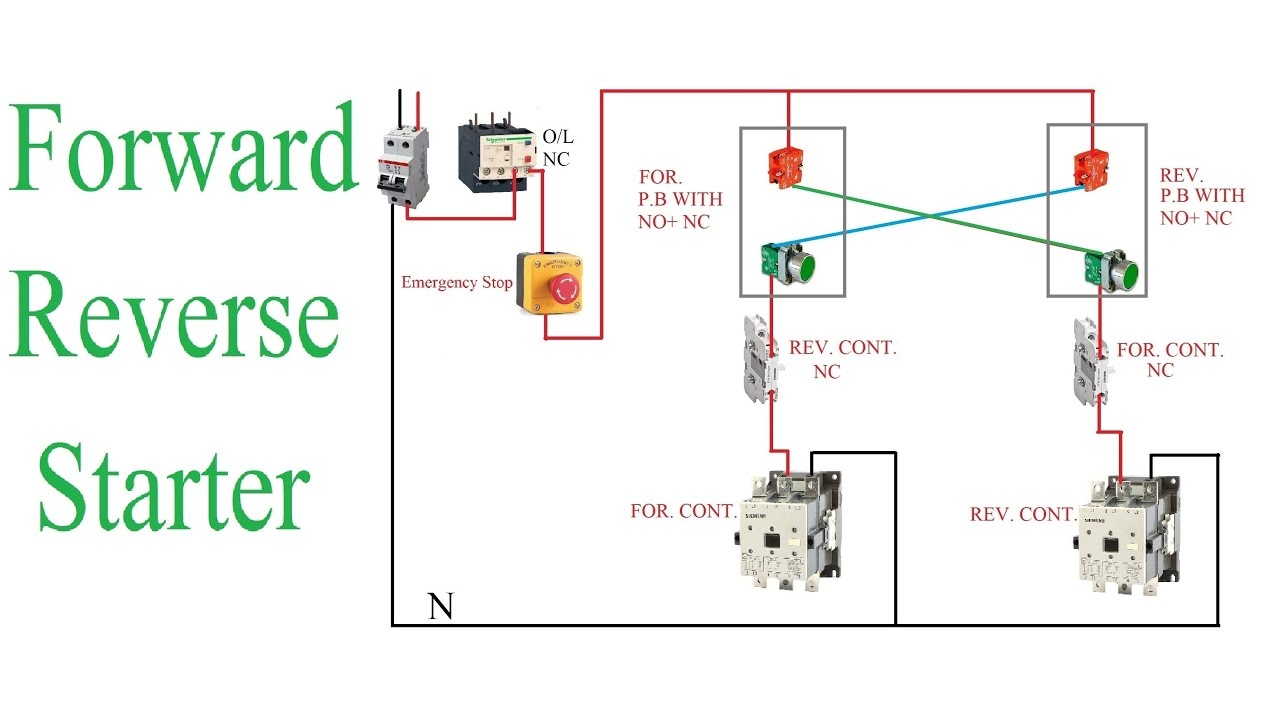
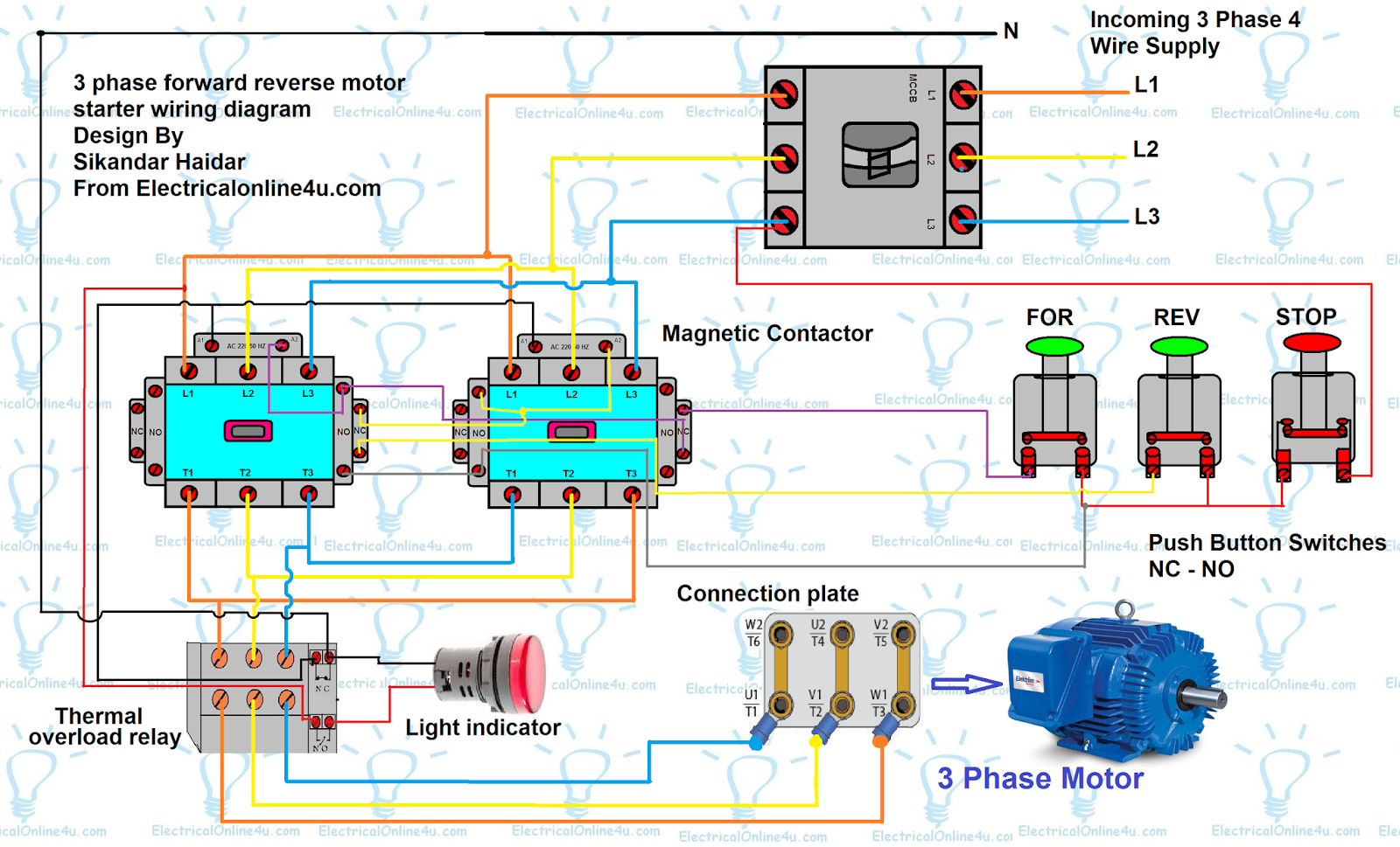
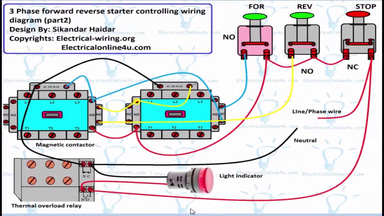
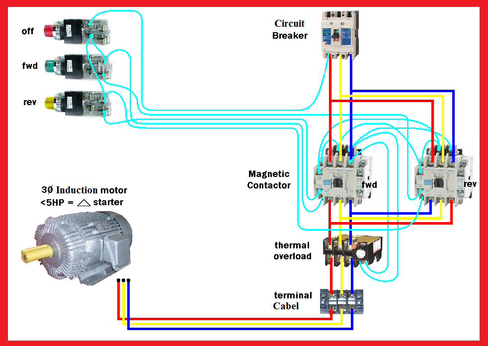
In the 3-phase motor forward reverse starter wiring diagram. I showed the 3 poles MCCB circuit breaker, 2 magnetic contactors, normally open, normally close push button switch, thermal overload relay, 3 phase 4 wire system supply, 3 phase motor with connection, trip indicator light, etc. In short, this is the complete guide to forward reverse.
Control Circuit Wiring Diagram
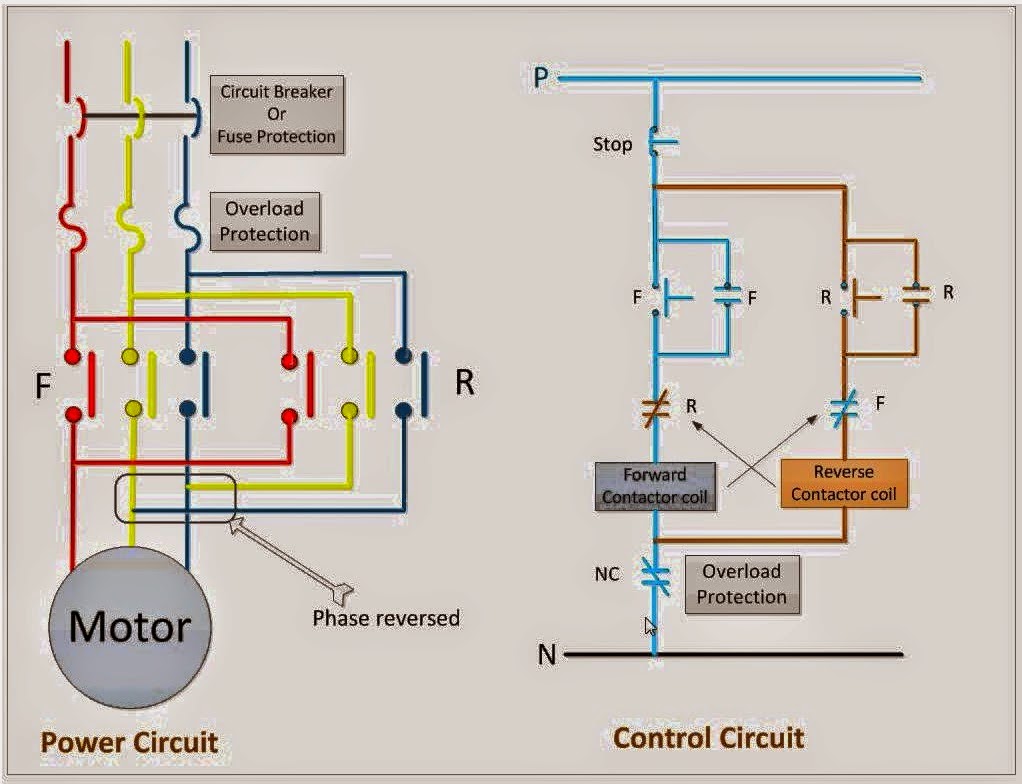
The reverse forward direction of a motor can be achieved using two contactor (K1 & K2) and relay. The K1 contactor is used to switch the three-phase power supply to the motor and run in clockwise direction. The K2 contactor is used to run the motor in anti-clock wise direction.
Forward Reverse Schematic Diagram
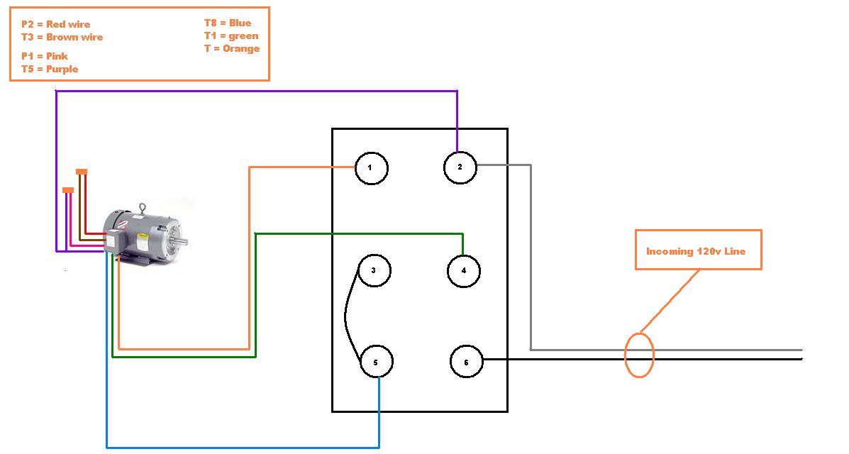
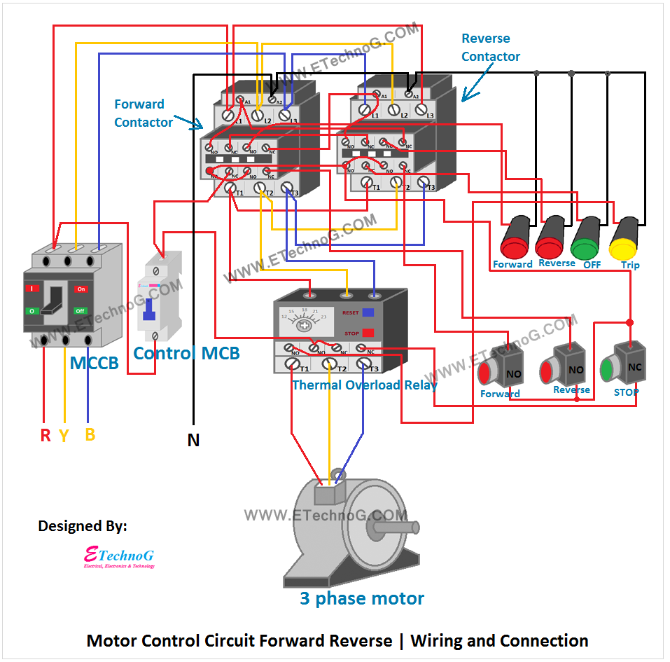
Step 1: Connect the motor's main power supply to the power terminals of the motor. Step 2: Connect the starter coil to the motor's main power supply. Step 3: Connect the starter switch to the starter coil. Step 4: Connect the forward and reverse switches to the starter switch. Step 5: Connect the motor leads to the starter switch.
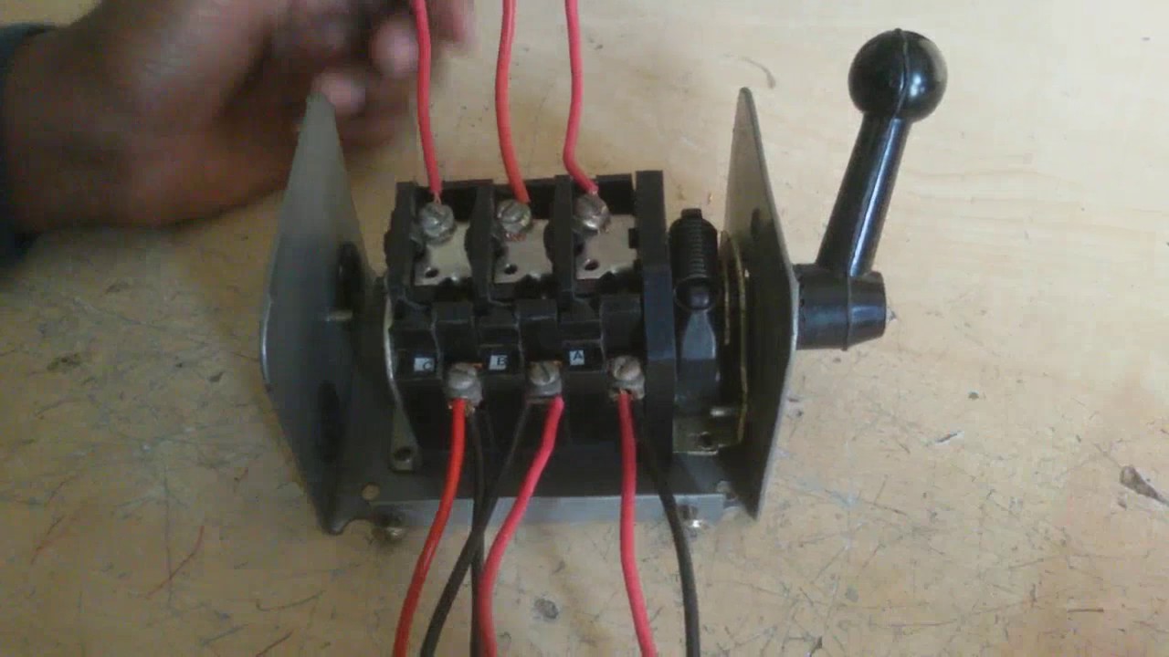
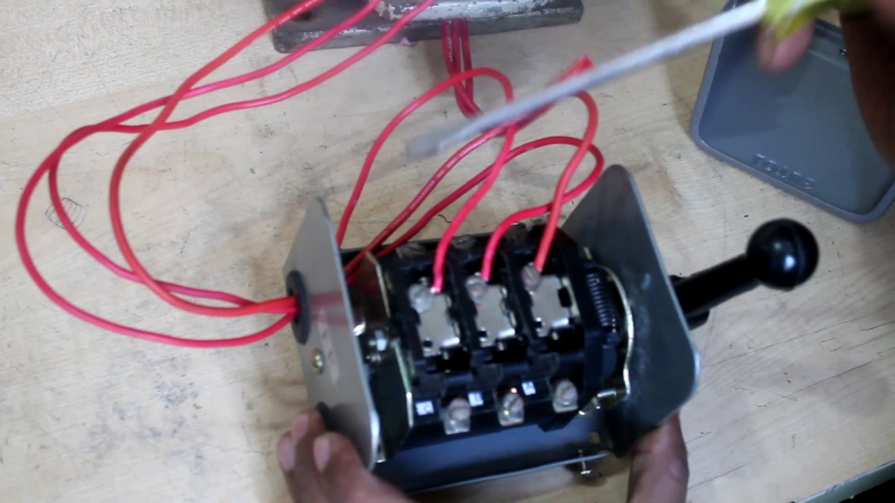
how to connect a three phase motor reverse and forward by change over
164 Share 18K views 4 years ago #contactor #motor #mcb This video shows 3 Phase Forward Reverse Switch Wiring Diagram. The forward reverse motor control is used in a system where.
How To Wire Single Phase Forward Reverse Swith / Need help setting up
One of the most popular methods of wiring a DC motor forward reverse switch is by using a "daisy chain" of wires. This involves connecting the positive lead of the motor directly to the positive terminal of the switch, then connecting the negative lead of the motor to the first terminal of the switch.
Motor Forward Reverse Wiring Diagram
ATO Automation 31.2K subscribers Subscribe Subscribed 190K views 3 years ago The structure of the 1-phase motor determines that the reverse rotation is generally completed by hardware. It is.