Gm Ac Compressor Wiring Diagram Sharp Wiring
HVAC system diagrams and schematics fall into three different categories: ladder, line, and installation diagrams. Here's how those break down. Ladder Diagrams. The ladder diagram is one of the easier ones to read. It lists the circuit connections and electrical wiring for the system. Because it explains electrical circuits, the diagram looks.

Ac Compressor Air Conditioner Wiring Diagram / Split Air Conditioner Wiring Diagram
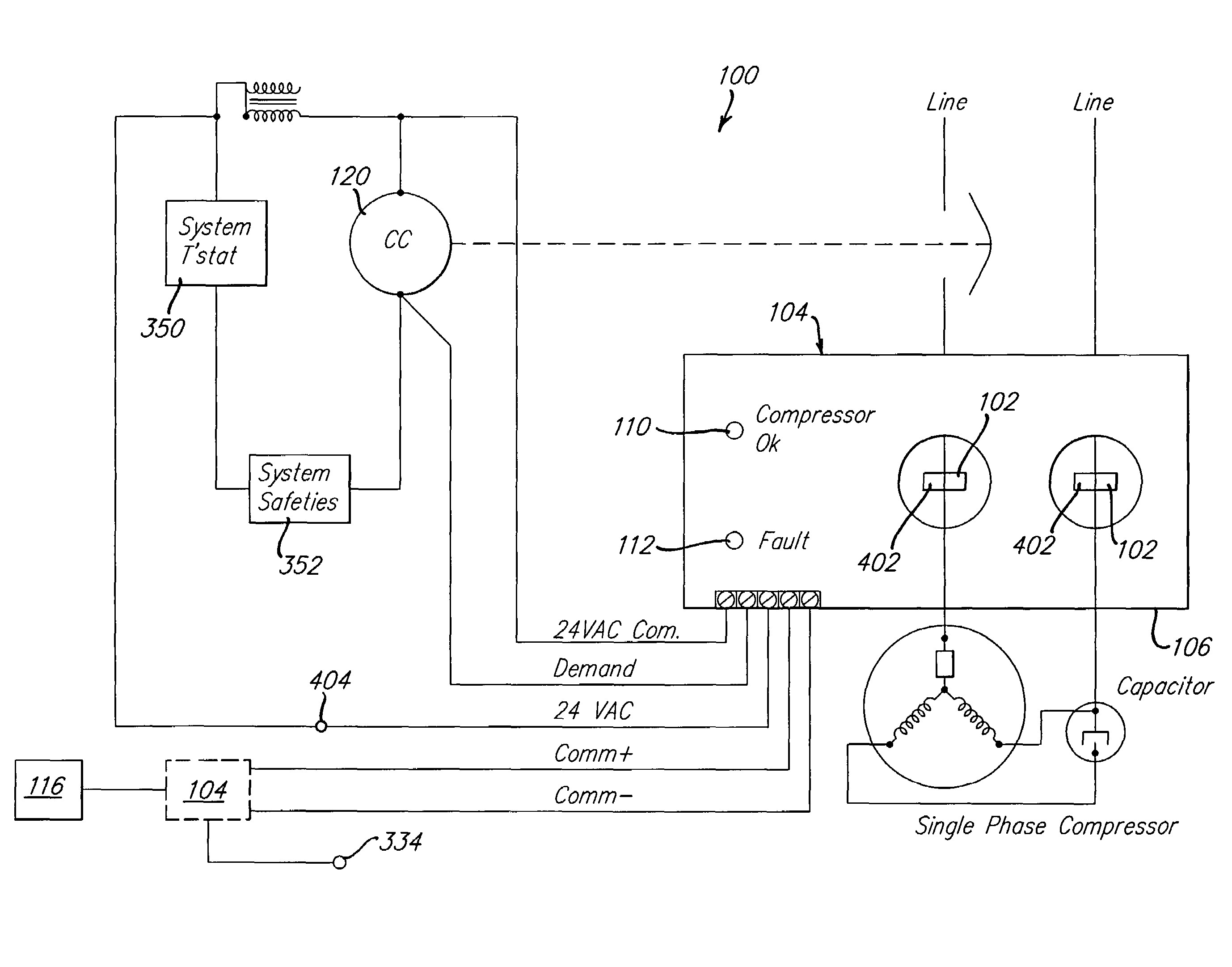
of compressor damage under abnormal system conditions. These devices limit damage to A/C components by making the system inoperable whenever a severely abnormal condition develops. When a returned compressor is analyzed for failure responsibility, the physical condition of the compressor is examined to determine if the compressor was

Wiring Diagram Hermetic Compressor / 28 Copeland Compressor Wiring Diagram Single Phase Wire
AC Cord. The AC cord of the air compressor is how you supply electricity (power) to your motor by plugging the cord into a suitable wall socket. Most compressors are designed to run on either 120 volts or 240 volts.. Two-Stage Air Compressor Diagram & Parts. Next up we have a two-stage stationary air compressor. Most of the parts of this.
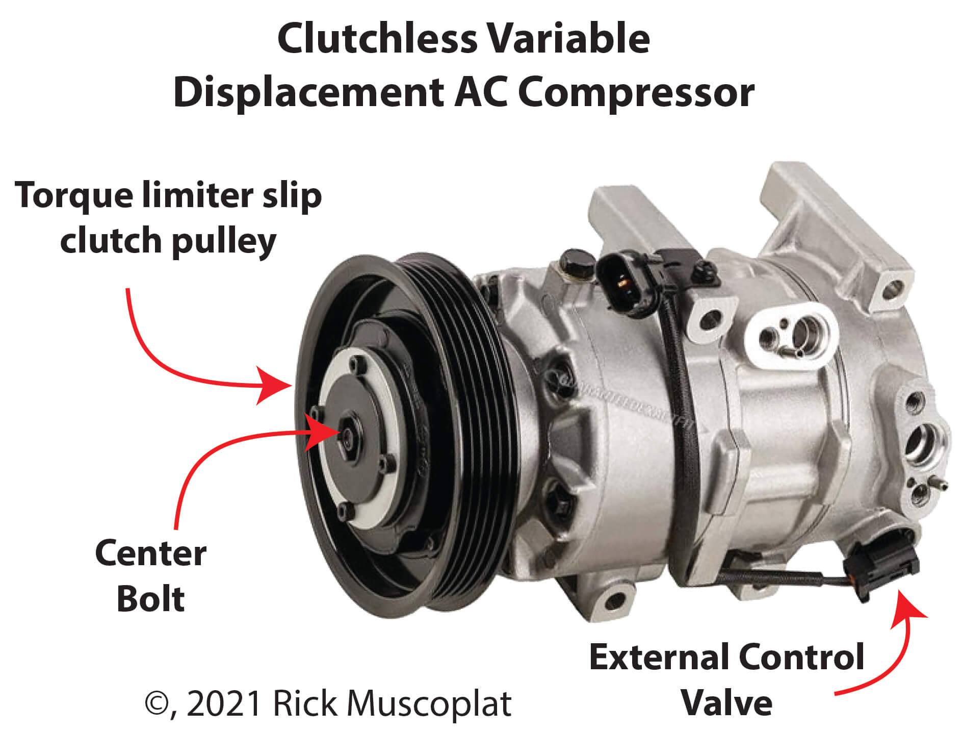
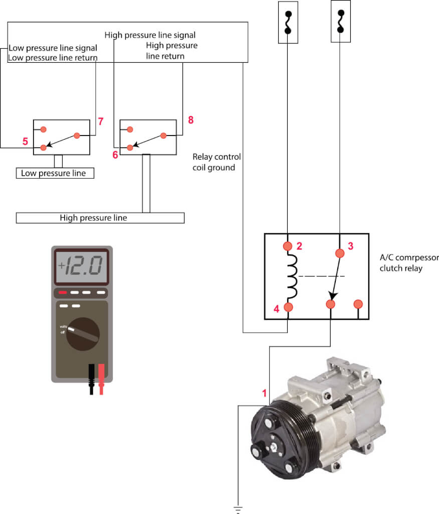
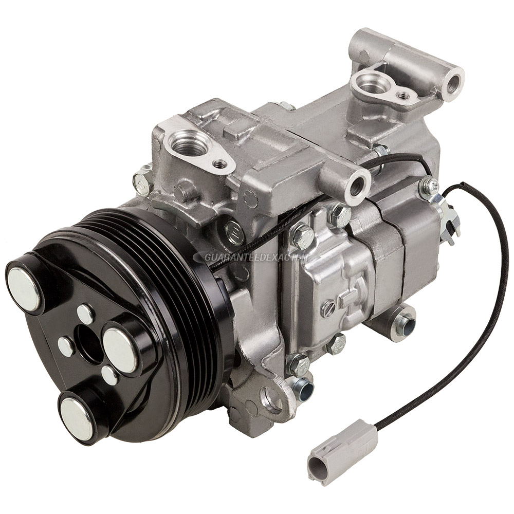
Clutchless AC Compressor — How it works — Ricks Free Auto Repair Advice Ricks Free Auto Repair
Air Conditioner Compressor Troubleshooting The average compressor in many residential air conditioner or heat pump condensing units.. This is a wiring diagram for a Lennox condensing unit and it indeed does show the run capacitor wired as you say it is supposed to be wired.

Home Ac Compressor Diagram / Mechanical Engineering AC Functional Diagram 832 ac compressor
An AC condenser releases heat that the refrigerant has removed from the home's air. The condenser is the main unit located outside the home. It resembles a box encased in thin metal fins. The compressor removes heat from refrigerant vapor, turning the refrigerant back to a liquid as it cools.
Ac Compressor Wiring Diagram Cadician's Blog
How to wire air conditioner compressor. This video shows you how to wire an HVAC ac compressor. I go over the location where each wire needs to go, where the.
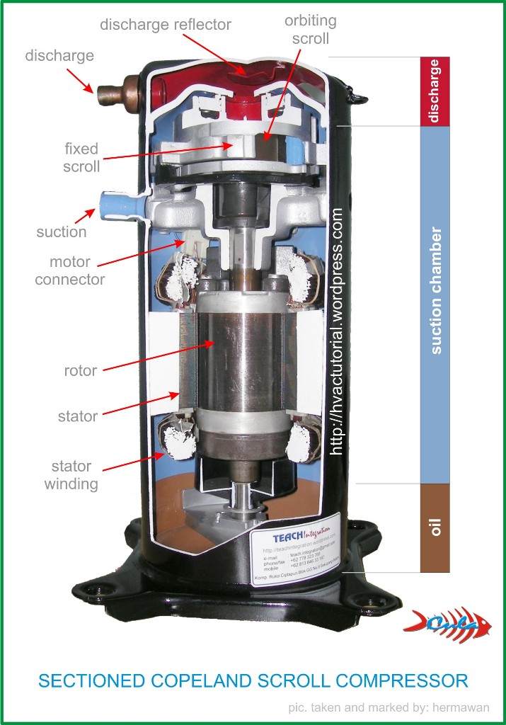
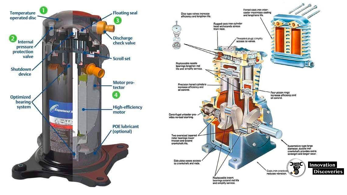
Compressors Mechanism TypesCopeland Scroll Compressor
Still, the major parts of an air conditioner manage refrigerant and move air in two directions: indoors and outside: Evaporator - Receives the liquid refrigerant. Condenser - Facilitates heat transfer. Expansion valve - regulates refrigerant flow into the evaporator. Compressor - A pump that pressurizes refrigerant.

How Does Car AC Compressor Work Process & Steps for Understanding
Specific refrigerants are needed as the working fluid in the refrigeration cycle. An air conditioner goes through 4 processes; compression, condensation, expansion, and evaporation. Typically, an air conditioner is made up of 4 major components; compressor, heat exchanger, fan, and expansion valve. AC Working Principle in Diagram.
Ac Compressor Wiring Diagram
Control circuits and a contactor relay turn on the outside compressor/condenser motor and its outdoor cooling fan as well. The air conditioning or heat pump compressor compresses the incoming refrigerant to a high pressure gas and moves that gas into the condensing coil described just below. Typically a piston moves up and down inside of a.
Copeland Ac Compressor Wiring Diagram Chic Aid
This is the piece of your air conditioning system that most people never see. It's contained in a metal box called a plenum, and sits on top of your furnace. If you have a horizontal furnace in an attic, the evaporator coil will sit on one end of the furnace instead of on top. The 'inside unit' or 'indoor coil' are other common names.

Parts of an Air Compressor More in Compressor, Air compressor
In the diagram above, the compressor (1) compresses the refrigerant vapor and moves it towards the condenser. The heat of compression raises the temperature of the refrigerant vapor causing it to be a high pressure superheated vapor. As this refrigerant moves into the condenser (2), the condenser rejects the heat in the refrigerant, causing it.

Diagram Of Ac Compressor / Air Conditioner Diagram Of Parts Automotive Parts I am
Now we will explain in detail about the various parts of AC. 1. Evaporator Coil: The evaporator coil, situated near the furnace, is a critical component in air conditioning systems. It works by circulating refrigerant through a network of copper tubing and fins.
Air Conditioner compressor Innovation Discoveries Automotive >
Damper. Drain Pan. Isolator Switch. 1. Refrigerant: ( Parts of AC ) Refrigerant is found inside your air conditioner's copper coils or curls. A refrigerant assists with the cooling function of your air conditioner, yet in addition a refrigerator, freezer, or whatever other appliance utilizes cooling.

Diagram Of Ac Compressor / Air Conditioner Diagram Of Parts Automotive Parts I am
Integrated Dryer (optional) 2. Coolant Filter 3. Coolant Separator Cartridge 4. Airend relief valve 5. Coolant Filter Plug 6. Sight Glass 7. Pilot Valve 8. Pressure Switch. The basic anatomy of air compressors, expolded view diamgrams, breakdowns, primary parts of piston and rotary screw.

A C Compressor Wiring Diagram Focus Wiring
A central air conditioner cools with an outdoor compressor and condenser coil connected to an indoor furnace fitted with an evaporator coil. ©Don Vandervort, HomeTips. Refrigerant circulates through copper tubing that runs between the evaporator and the condenser. This refrigerant receives and releases heat as it raises and lowers in.

Pin by Israel Josue on hvac Refrigeration and air conditioning, Rotary compressor, Air
To do that, a compressor puts the gas under high pressure, a process that creates unwanted heat. All the extra heat created by compressing the gas is then evacuated to the outdoors with the help of a second set of coils called condenser coils, and a second fan. As the gas cools, it changes back to a liquid, and the process starts all over again.