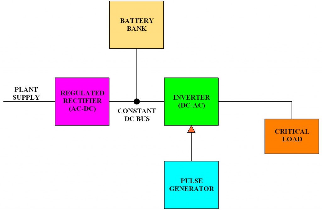
Power Supply Block Diagram Headcontrolsystem
Block Diagram of Power Electronics We have already discussed that majorly power electronics deals with conversion and controlling of a large amount of electric power. This means the converter and controller are its two major components.

What is Power Electronics? Power vs Linear Electronics & Uses
Primary transmission. The electric power at 132 kV is transmitted by 3-phase, 3-wire overhead system to the outskirts of the city.This forms the primary transmission. Secondary transmission. The primary transmission line terminates at the receiving station (RS) which usually lies at the outskirts of the city.At the receiving station, the voltage is reduced to 33kV by step-down transformers.

Basic wind turbine generator block diagram [9]. Download Scientific Diagram
In this video Block Diagram of a Power Electronic System is discussed in detail.Material (Notes):https://drive.google.com/file/d/106ZjBgkW3-QkL3oLFHo6g-4abyI.
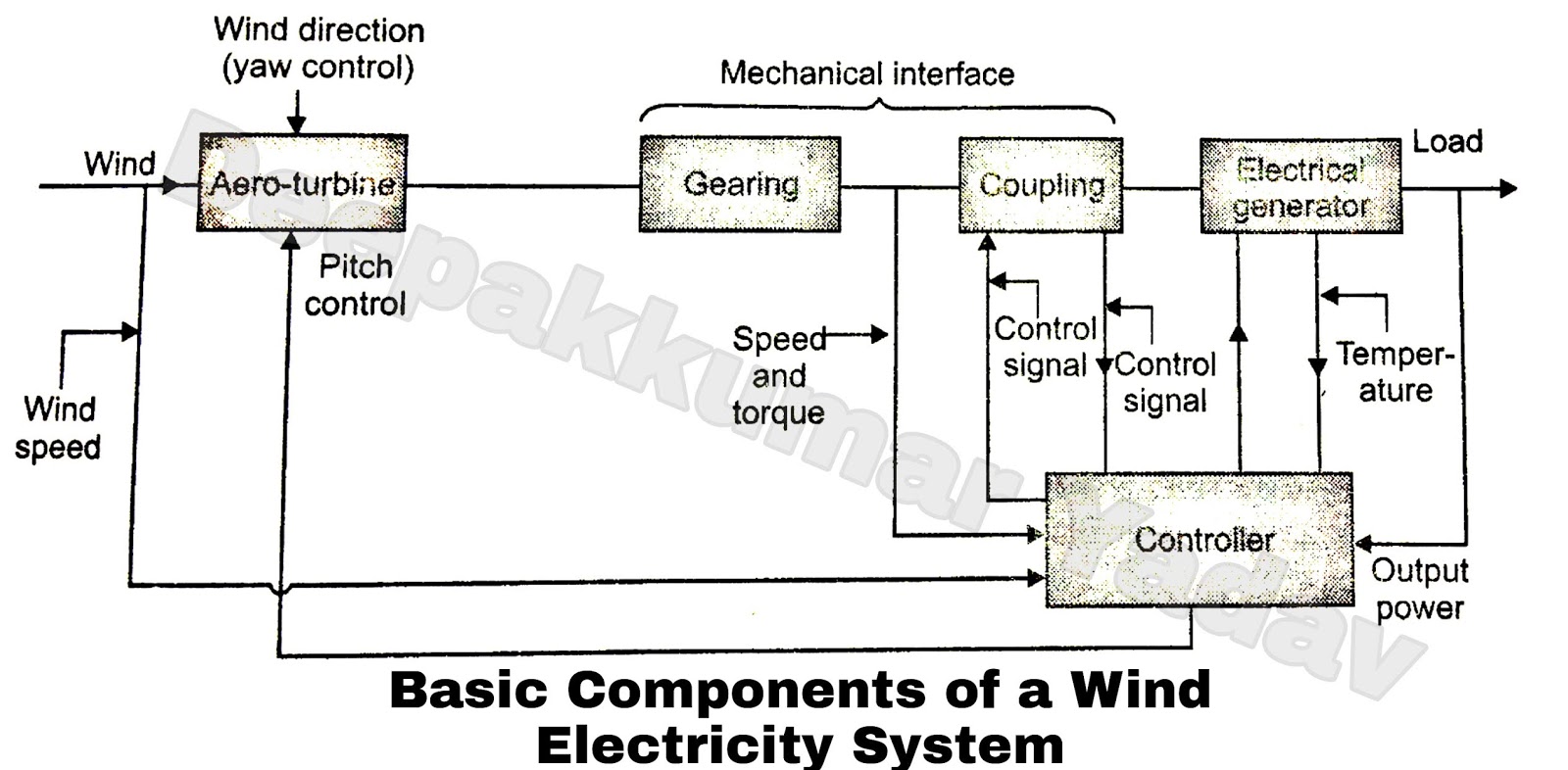
Block Diagram and Working of Wind Energy Plant and its Applications
An electrical power grid is an interconnected network that delivers the generated power to the consumers. It is, sometimes, also called as an electrical power system.A power grid consists of generating stations (power plants), transmission system and distribution system. Power generating stations are located at feasible places - according to the availability of the fuel, the dam site or an.

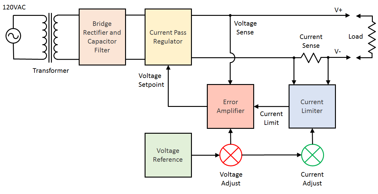
Block diagram of a power supply system with an unregulated input... Download Scientific Diagram
Simplified Block Diagram of a Power Electronics System Power Electronic "Power" Circuit Feedback "Control Circuit" Load1 Load2 Loadn Electrical Inputs "Sources" Electrical or Mechanical Output "Loads" x 1 x 2 x m y 1 y 2 y n f 1 f 2 f k. Detailed Block Diagram of Power Electronics System Filter & Rectify PE Circuit Load Filter & Rectify Control.
Portable Variable Power Supply Part 1
1. KVA rating; 2. Rated voltages; ADVERTISEMENTS: 3. Number of phases (single or three phases); 4. Rated frequency; 5. Connections (Δ or λ in case of 3-phase transformer); 6. Tappings if any;

Block diagram of a power system Download Scientific Diagram
2.3+ billion citations. Join for free. Download scientific diagram | Block Diagram of a Power Electronic System from publication: An interactive educational learning tool for power electronics.

2 Block diagram of electrical power system. Download Scientific Diagram
POWER SYSTEM OPERATION AND CONTROL DIGITAL NOTES B.TECH. Fig1.4:The block diagram representation of the Generator and load The turbine can be modeled as a first order lag as shown in the Fig1.5 Fig1.5.The turbine model Gt(s) is the TF of the turbine; ∆PV(s) is the change in valve output (due to action)..

Block diagram of twoarea interconnected power system. Download Scientific Diagram
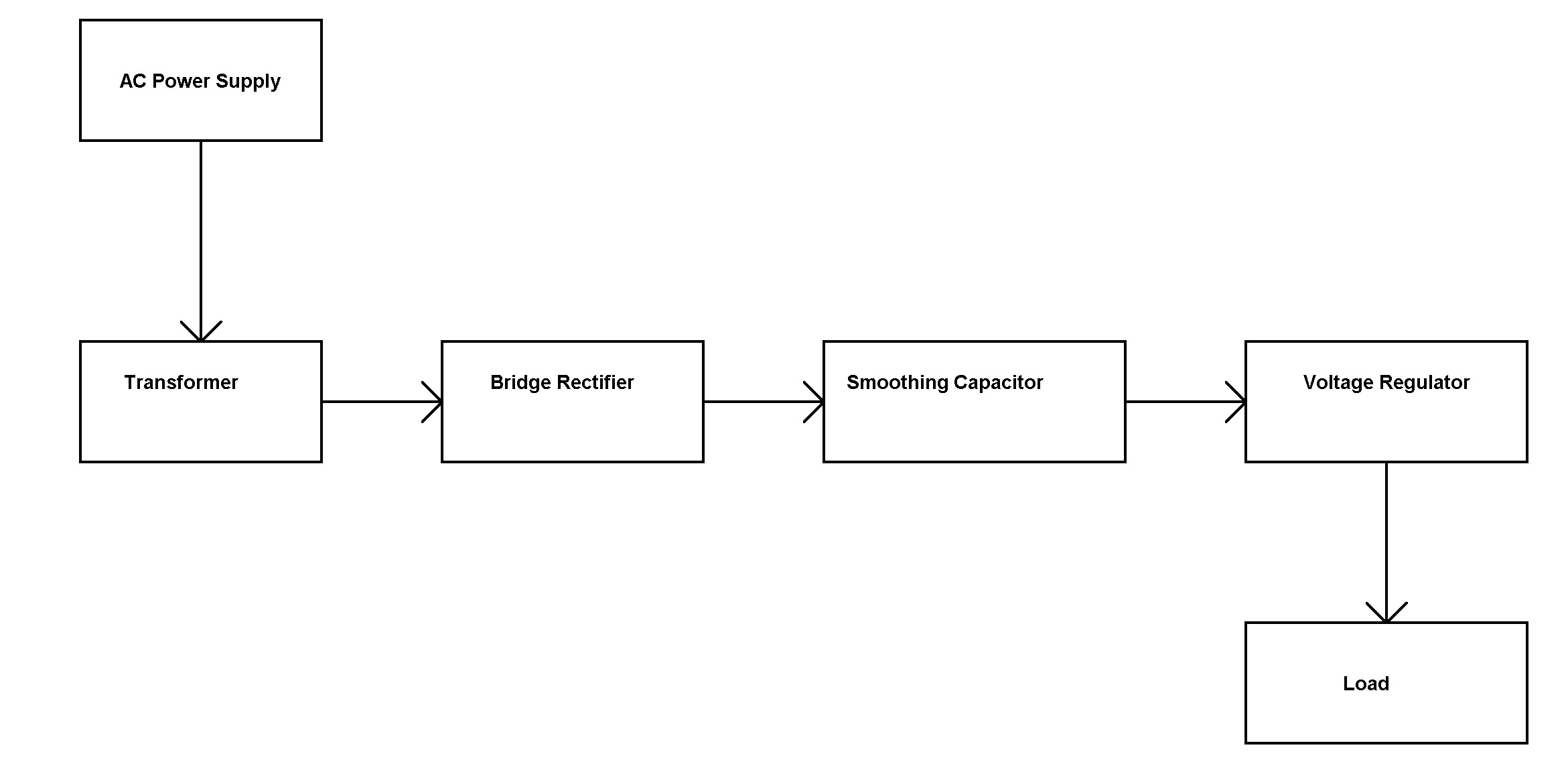
In the power supply block diagram, the input voltage is 230 Volts however in practice; there are significant differences within the AC supply mains voltage. As this mains supply voltage is i/p to the normal power supply, the bridge rectifier's filtered o/p is approximately directly proportional toward the AC mains voltage. The source.
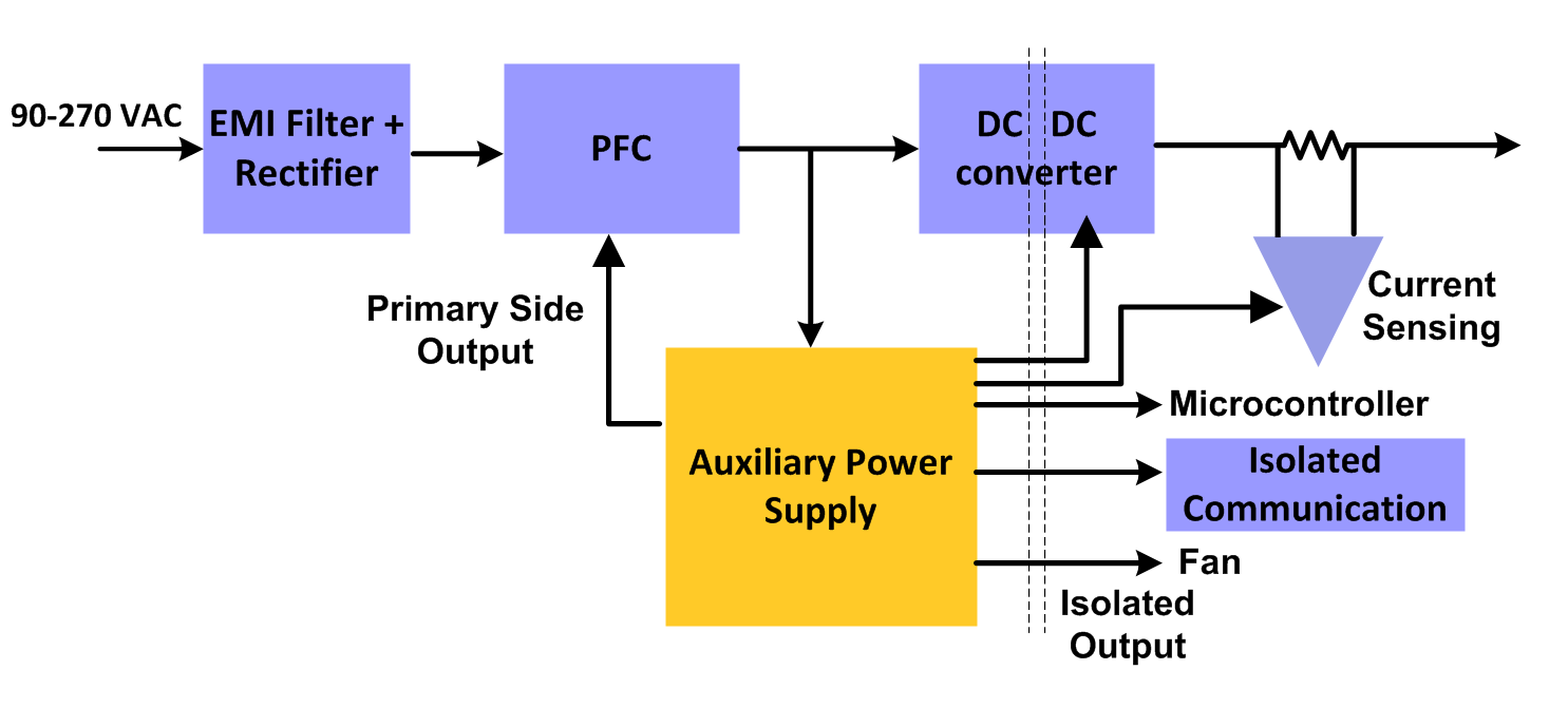
Common challenges when choosing the auxiliary power supply for your Server PSU Industrial
Power Supply block diagram parts Electrical Transformer The electrical transformer receives on the primary winding an AC voltage and delivers on the secondary winding a different AC voltage (a lower one). This AC output voltage must be according to the DC voltage we want to obtain at the end.

Solar energy monitoring system using iot Ericvisser
Determination of the Average Daily PV System Load. 1. Identify all loads to be connected to the PV System. 2. For each load determine its voltage, current, power and daily operating hours. For some loads the operation may vary on a daily, monthly or seasonal basis. If so accounted by calculating daily averages.
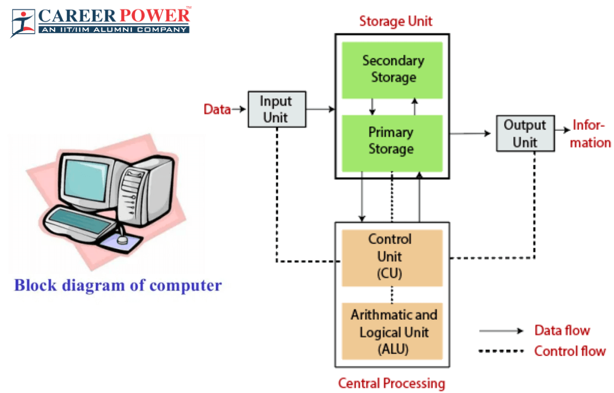
Block Diagram of a Computer
What is the electric power system? From a general perspective, an electric power system is usually understood as a very large network that links power plants (large or small) to loads, by means of an electric grid that may span a whole continent, such as Europe or North America.
Block Diagram Vs Circuit Diagram
Definition: Single line diagram is the representation of a power system using the simple symbol for each component. The single line diagram of a power system is the network which shows the main connections and arrangement of the system components along with their data (such as output rating, voltage, resistance and reactance, etc.).

Block Diagram of Load Frequency Control (LFC) of TwoArea Power System... Download Scientific
An electric power system or electric grid is known as a large network of power generating plants which connected to the consumer loads. As, it is well known that "Energy cannot be created nor be destroyed but can only be converted from one form of energy to another form of energy".

Block diagram of an interconnected power system a Twoarea multiunit... Download Scientific
Download scientific diagram | Block diagram of power system stabilizer. from publication: Robust Coordinated Design of PSS and TCSC using PSO Technique for Power System Stability Enhancement.
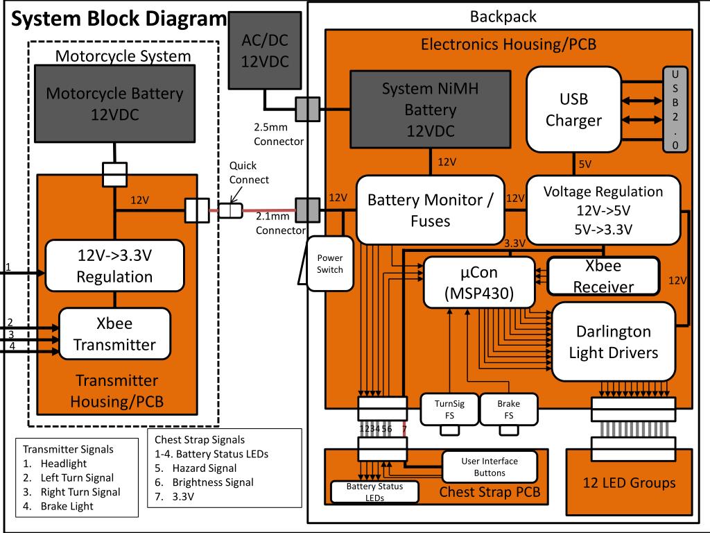
PPT System Block Diagram PowerPoint Presentation, free download ID6510336
A block diagram is a graphical method of representing the relationships among variables in a system.