
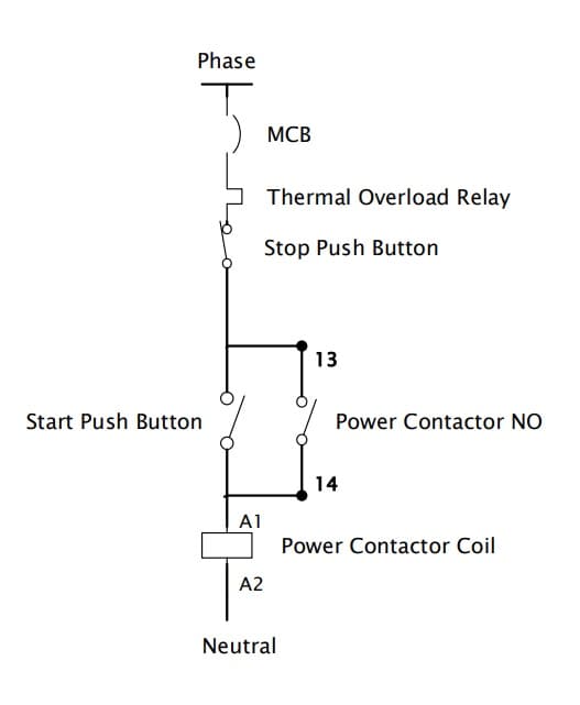
Dol Starter Wiring Diagram For Single Phase Motor
A DOL starter (also known as a direct on line starter or across the line starter) is a method of starting a 3 phase induction motor. In a DOL Starter, an induction motor is connected directly across its 3-phase supply, and the DOL starter applies the full line voltage to the motor terminals.

Dol Starter Remote Control Wiring Diagram
2- Control and connection diagram of single phase starter. 3- Working principal of single phase DOL starter. DOL single phase working principle is two types as manual and auto mode. Both below mentioned details. 1- Manual Mode: First check the voltage in voltmeter. Press the start push button then contactor coil is energized.

Schematic Diagram Of Dol Starter My XXX Hot Girl
Raja+ DOL Starter (Self reset) Selection of Starter • Refer Table A for recommended selection of 3TW72 starters. Table A: kW/HP Rating, thermal overload relay range & fuse rating, Coil Voltage, Maximum full load current for different types of motors. • Recommended Submersible pump rating 5.5kW/7.5HP IS/IEC 60947-4-1Max. 3 4 5 1 6 2 7 3 13.
Automobile Starter Motor Circuit Diagram
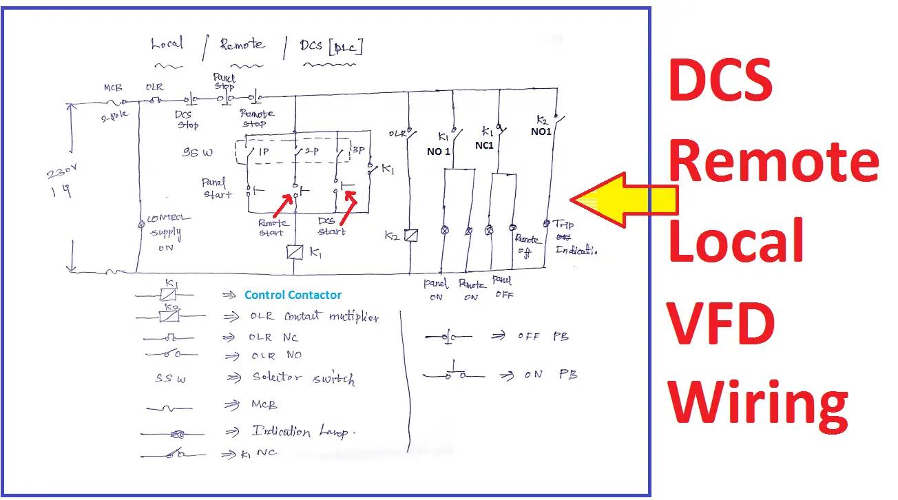
In this video we explain dol starter local and remote wiring connection with diagram, this type of wiring required when we need to control our motor from two.
10+ Wiring Diagram Of Dol Starter Robhosking Diagram
Direct-on-Line (DOL) Starter. It is an easiest method for starting up three phase induction motor in which stator windings of the motor are connected directly to the main supply. When an induction motor is connected to the three phase supply, a very large current typically 5 to 8 times the full load current flows through the motor.

Dol Starter Circuit Wiring Diagram
dol starter diagram for A 3-Phase Motor. A Direct-On-Line (DOL) starter is a common method used for starting 3-phase induction motors. It provides full voltage to the motor terminals right from the start, allowing the motor to reach full speed quickly.. Remote Control: A contactor allows for remote control of the motor. The start and stop.
Dol Motor Wiring Diagram Irish Connections
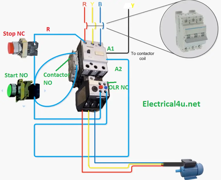
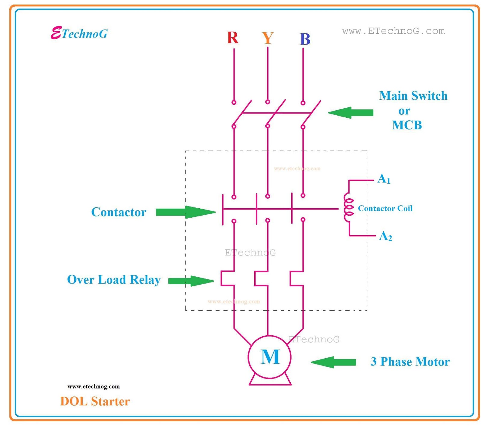
This video is about the 3 phase dol starter control and main wiring animation with MCCB, magnetic contactor, thermal overload relay, NC NO switches, motor connection using a simple step by step.
Dol Circuit Wiring Diagram Three Phase Motor Control Circuit Diagram Pdf New Simple Contactor
DOL stands for Direct On-Line. The DOL starter is one of the types of Motor starter which connects the motor to the line voltages directly. To start the induction motor in the simplest and cheapest way this type of starter is used. In this type of starter, terminals of the motor are connected to the power supply through a contactor, circuit.

Mobile Pump Starter Circuit Diagram
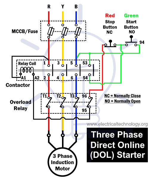
DOl Starter Control Diagram (Three Phase) :. But there is a condition for remote control based switching that one should know, that all the remote "OFF" push buttons always be connected in series with "OFF" pushbuttons of the starter and vice versa (all the remote "ON" push buttons always be connected in parallel to "ON.
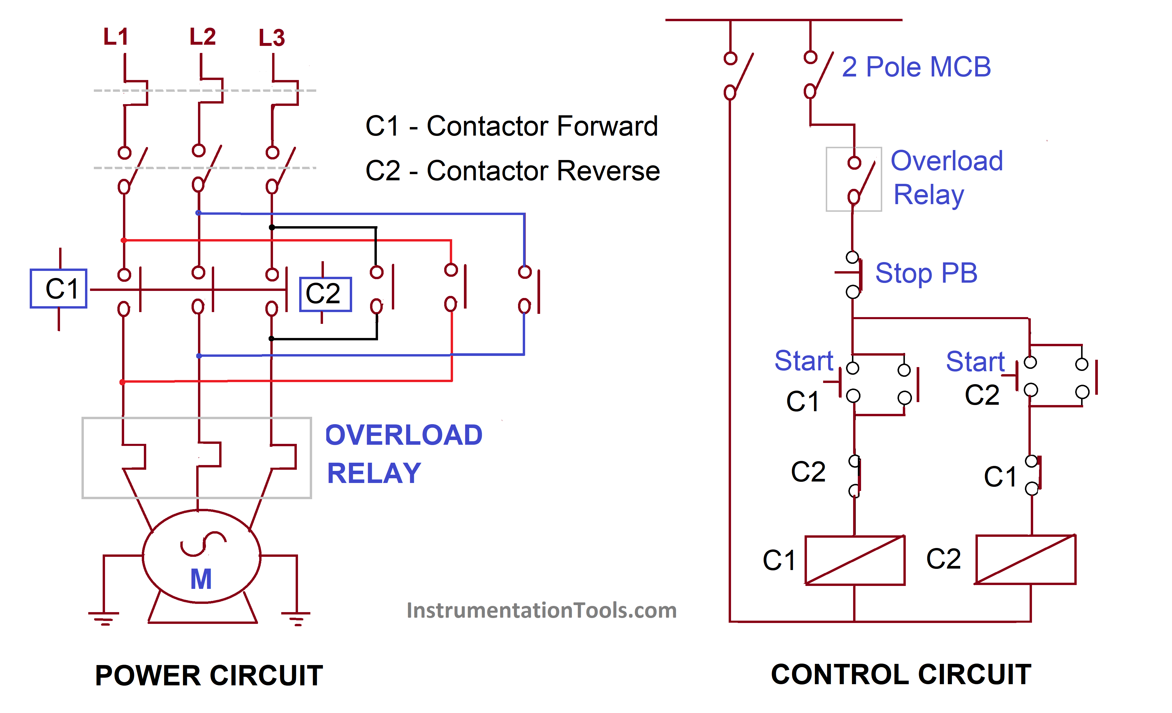
control circuit diagram of forward reverse starter Wiring Diagram and Schematics
LEARN ALL ABOUT DOL STARTERLearn about DOL starter power diagram, control diagram with animation in this video we have explained all details about DOL starte.
sprite wiring diagram
What is meant by an electrical starter? The electrical motor starter is nothing but a combination of electrical equipment uses to accelerate the electrical motor at the rated RPM (revolution per minute). It works based on Faraday's electromagnetic principle. Learn More: Cheap DOL starter - DCS/Remote/Local Start/Stop
[Download 29+] Dol Starter Control Circuit Diagram Explanation
What is Direct Online (DOL) Starter? Protection Offered by DOL Starter: Construction of DOL Starter: Parts of DOL Starter: DOL Starter Wiring Diagram: Three Phase DOL Starter Wiring Diagram: Single Phase DOL Starter Wiring Diagram: Working of DOL Starter: Principle of DOL Starter: Features , Advantages/Disadvantages & Applications of DOL Starter
DOL StarterWorking, Control Circuit Wiring Diagram Electricalsblog
Any control machine that uses electric motors has contactors that are used to control them. For single-phase motors, 230 V-rated coils are used. For three-phase motors, 415 V-rated coils are used.. DOL Starter Wiring Diagram . Figure 2. DOL starter wiring diagram. Image used courtesy of Simon Mugo . Starting Characteristics .

[DIAGRAM] Control Wiring Diagram Of Dol Starter FULL Version HD Quality Dol Starter
Published on 2022-12-21 Download Download EdrawMax Edit Online A diagram is provided for clarity when wiring a DOL starter with an indicator. This diagram will show how the components of the DOL starter should be connected in order to create the desired control system.

Dol Connection Circuit Diagram
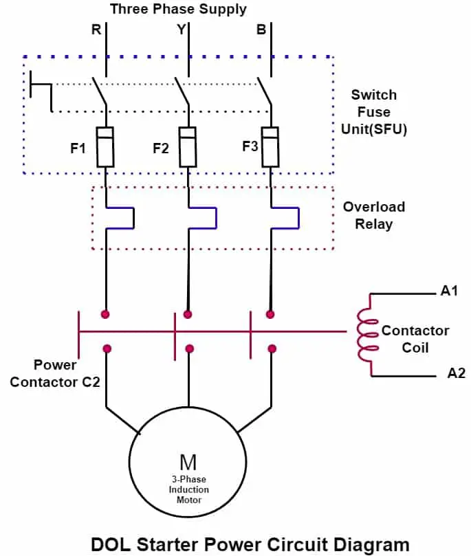
The Direct On Line Motor Starter (DOL) consist a MCCB or Circuit Breaker, Contactor and an overload relay for protection. Electromagnetic contactor which can be opened by the thermal overload relay under fault conditions.

DOL Starter Local and Remote Control with Selector Switch Connection ElectricalTechnician YouTube
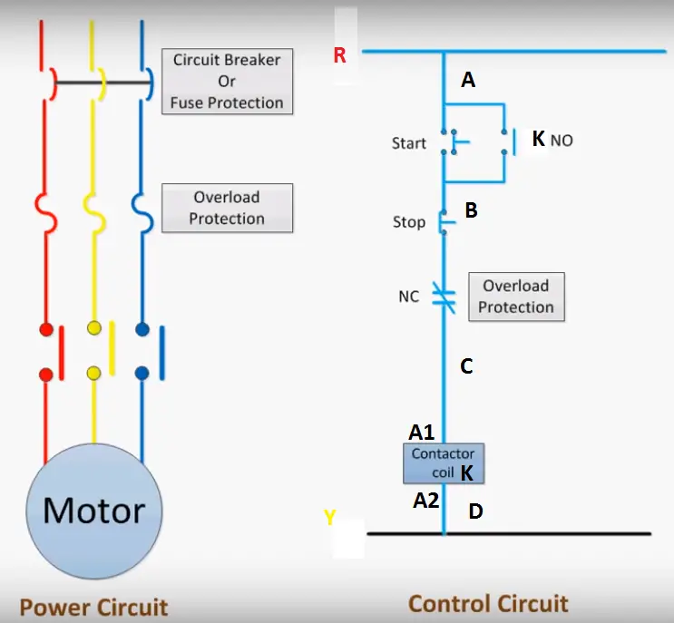
Direct on line Starter. Fig. 1 (a) shows a typical direct on line starter called DOL starter suitable for a small squirrel cage induction motor consisting of a magnetic contactor and thermal overload relay and Fig. 1 (b) shows a schematic wiring diagram for its control circuit. When start push-button is pressed, the contactor coil is energised.
