
Verilog Code For Traffic Light Controller PDF Computer Science
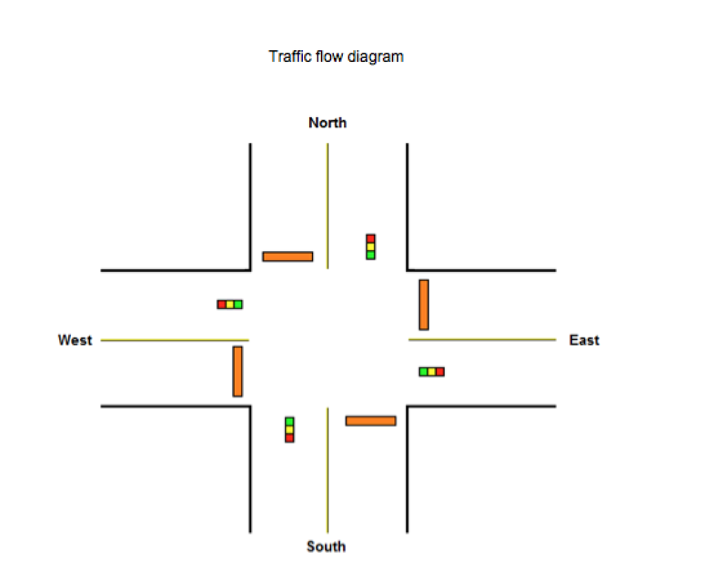
Given below code is design code for Traffic Light Controller using Finite State Machine (FSM). In this clk and rst_a are two input signal and n_lights, s_lights, e_lights and w_lights are 3 bit output signal. In output signal, "001" represents Green light, "010" represents Yellow light and "100" represents Red light.

Simple Traffic Light Controller Verilog gicha web
Traffic Light Controller Using Verilog The purpose of this project is to design a methodology using Verilog to control the traffic with specified time delays for a T-Shaped road.* Table of Contents Introduction Methodology Directions Considered Problem Statement State Diagram State Table

GitHub RamitDutta/Designof4WayTrafficLightControllerBasedon
Star 1 Code Issues Pull requests In this Project, a sophisticated traffic light controller was developed using Verilog and was implemented on an FPGA (Field-Programmable Gate Array) platform. The primary aim was to simulate a realistic traffic management system, employing a Moore state machine design paradigm.

Verilog Tutorial 26 Traffic Lights 02 YouTube
This is my first Verilog Project. It includes analysis and design of a T intersection traffic lights and then code is written in Verilog HDL language.PLEASE.

GitHub Devipriya1921/TrafficLightControllerusingVerilog Verilog
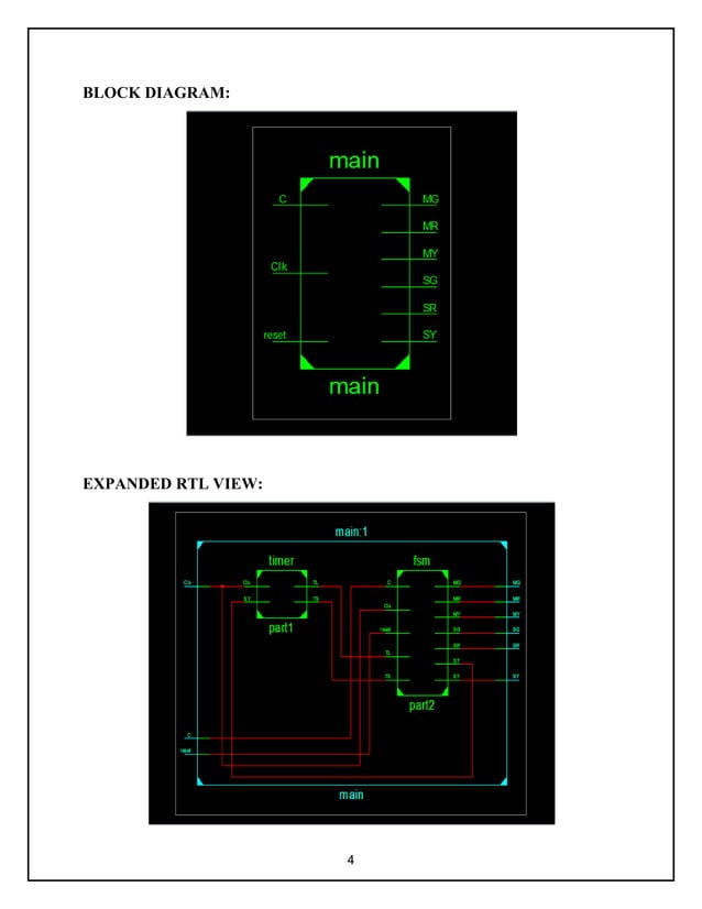
Example: traffic light controller. specify state bits and codes for each state as well as connections to outputs. structural Verilog (same as a schematic drawing) traffic light controller timer ST TS TL machines advance in lock step initial inputs/outputs: X = 0, Y = 0 CLK

57 Traffic Light Controller in Verilog YouTube
The objective of this project is to develop a traffic light control system using Verilog and Proteus. The algorithm for doing this is based on Finite State Machine (FSM) . Demonstration Video link Contents Softwares Used Description Extra Features State Diagram Description of States Flowchart Emergency condition Jam Condition
4 Way Traffic Light Verilog Code ourfasr
Traffic Light Controller Using Verilog The purpose of this project is to design a methodology using Verilog to control the traffic with specified time delays for a T-Shaped road.* Table of Contents Introduction Methodology Directions Considered Problem Statement State Diagram State Table RTL Code RTL Schematic View TESTBENCH Output Waveforms Result
Smart traffic light controller using verilog
About Press Copyright Contact us Creators Advertise Developers Terms Privacy Policy & Safety How YouTube works Test new features NFL Sunday Ticket Press Copyright.

Electrical Traffic Light Verilog Code Valuable Tech Notes
Please like and subscribe our channel for any latest update. To view verilog code and vivado file visithttps://guideforu.in/traffic-light-controller-using-ve.

Lecture 33 Verilog HDL Traffic Signal/ Light Controller using state
Verilog designing is hardware descriptive language, the name itself suggest that it deals with the hardware designing and simulation. Basically, it becomes very difficult to mount the various electronic components on breadboard or PCB circuit.
VLSICoding Design Traffic Light Controller using Verilog FSM Coding
-1 I am working on a traffic light code and the code seems to be working fine in simulation, but when implemented on the FPGA the colors do not seem to toggle from yellow to red for the main street (sc) and green to yellow to red for the crosswalk street (st). It's a simple 4-way street.

[PDF] An Advanced Traffic Light Controller using Verilog HDL T
91 6.6K views 3 years ago Verilog HDL Traffic signal controller Verilog code PART I for Part 2: • Traffic Signal Controller : verilog S..more.more Traffic signal.

Traffic Light Controller with Verilog Code and FSM on Xilinx Vivado
FPGA is a re-configurable integrated circuit that consists of two dimensional arrays of logic blocks and flip-flops with an electrically programmable interconnection between logic blocks.\nThe reconfiguration property enables fast prototyping and updates for hardware devices even after market launch.

Verilog Tutorial 25 Traffic Lights 01 YouTube
A Verilog source code for a traffic light controller on FPGA is presented. A sensor on the farm is to detect if there are any vehicles and change the traffic light to allow the vehicles to cross the highway. Otherwise, highway light is always green since it has higher priority than the farm. Verilog code for traffic light controller:

Figure 3 from FPGA Implementation of an Advanced Traffic Light
Smart traffic light controller using verilog Feb 23, 2022 • 6 likes • 5,616 views V VaishaliVaishali14 Student Engineering This project will provides a detailed explanation about a smart traffic light controller using verilog code along with test bench and the working principle and simulation outputs are been attached.

4 way traffic light verilog code etjza
Next: Example - buffer allocation Up: Synchronous Verilog Previous: Embedded assertions Example - traffic light controller. This example is a controller that operates the traffic lights at an intersection where two-way street running north and south intersects a one-way street running east.