
Block diagram of the ECG SoC [7] Download Scientific Diagram
Full-featured ECG functional block diagram. Features Understanding the required electronic components for an ECG is easier if it is separated into the analog front-end (AFE), which digitizes these signals, and "the rest of the system," which analyzes, displays, stores and transmits the data.

The functional block diagram of ECG IC Download Scientific Diagram
This is seen in ECG 'A' below; ECG 'B' shows the treatment for 3rd degree AV block; i.e., a ventricular pacemaker. The location of the block may be in the AV junction or bilaterally in the bundle branches. AV Dissociation (independent rhythms in atria and ventricles) Not synonymous with 3rd degree AV block, although AV block is one of the causes.
Heart Block Dysrhythmias EKG Lesson 316
This Osmosis High-Yield Note provides an overview of Electrocardiography essentials. All Osmosis Notes are clearly laid-out and contain striking images, tables, and diagrams to help visual learners understand complex topics quickly and efficiently. Find more information about Electrocardiography: ECG basics. ECG rate and rhythm.
PPT BME 311 BIOMEDICAL INSTRUMENTATION I Lecturer Ali Işın
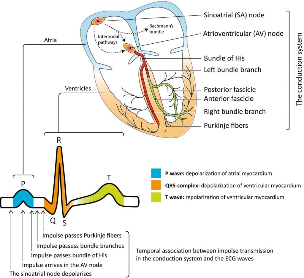
Section 1, Chapter 1 In Progress Cardiac electrophysiology and ECG interpretation Chapter contents Show Principles of cardiac electrophysiology and electrocardiography (ECG) To ensure effective cardiac pumping function, the atria and the ventricles must be activated rapidly and sequentially.
PPT Electrocardiographs ECG part 3 PowerPoint Presentation, free
This chapter discusses third-degree AV block, which is synonymous with AV dissociation, complete AV block, AV block III and AV block 3. In third-degree AV block, no atrial impulses are conducted to the ventricles. The atria and the ventricles are electrically dissociated from each other. This condition is referred to as atrioventricular (AV.

ECG Recording Setup (Block Diagram and Waveform) Electrical4U
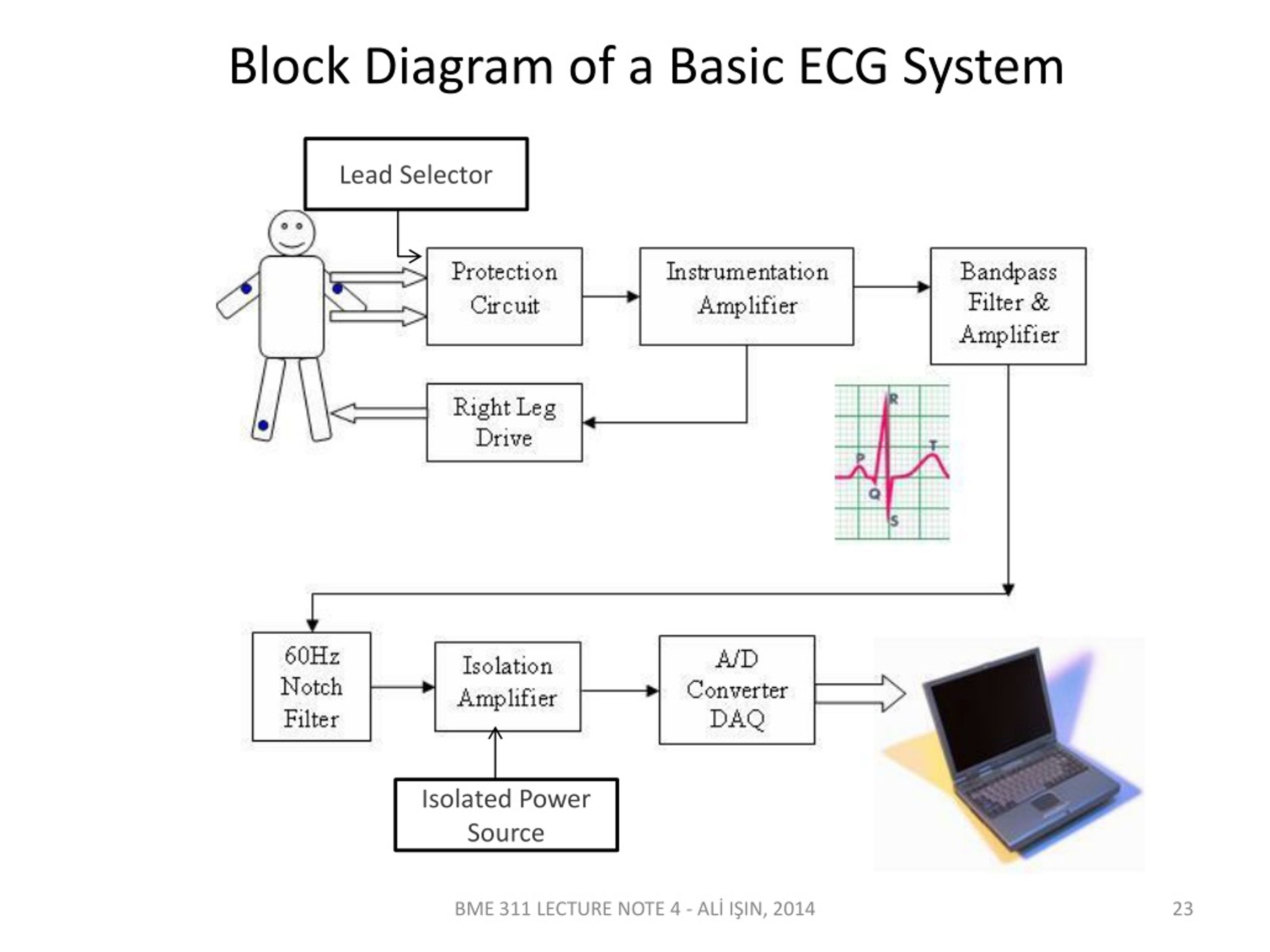
ECG Recording Setup Block Diagram Defibrillator Protection Circuit The one end of the electrode leads are connected along RA, LA, chest and LL of the patient. The other end of electrode passes through defibrillator protection circuit. The protection circuit has buffer amplifier and over-load voltage protection circuit. Lead Selection Logic

Block diagram of proposed ECG system. Download Scientific Diagram
It is used to record the electrical activity of the heart from different angles to both identify and locate pathology. Electrodes are placed on different parts of a patient's limbs and chest to record the electrical activity. Parts of the ECG explained P waves P waves represent atrial depolarisation.

Block diagram of portable real time DSP system for wireless ECG
Electrocardiography (ECG) is the interpretation of the electrical activity of one's heart over a period of time. Recently, there has been increased interest and demand in ECG measurement devices called Electrocardiograms (also abbreviated ECG) for use in the medical and research fields.

PowerPoint tutorial How to draw ECG block diagram in PowerPoint YouTube
Many of the ECG rhythm strips come from the collection of the late Dr. Alan Lindsay, master teacher of electrocardiography. Most of the 12- and 6-lead ECGs were recorded at LDS Hospital in Salt Lake City, Utah. Marquette Electronics has also given permission to use ECG rhythms and diagrams from their educational posters.
PPT Patient Monitor (Bedside Monitor) PowerPoint Presentation ID
1 st degree AV block 2 nd degree AV block 3 rd degree AV block The atrioventricular (AV) conduction system and AV blocks The AV system consists of the atrioventricular node (AV node) and the His-Purkinje system. These structures conduct the atrial impulse to the ventricles. Impulse conduction through the atrioventricular node is slow.
Clinical electrocardiography and ECG interpretation ECG interpretation
View the TI Electrocardiogram (ECG) block diagram, product recommendations, reference designs and start designing.

Block diagram of the proposed ECG monitoring device Download
The delay between activation of the RV and LV produces the characteristic "M-shaped" R wave seen in lateral leads. Delayed overall conduction time to the LV extends the QRS duration to ≥ 120 ms. Sequence of conduction in LBBB: 1) Conduction delay means impulses travel first via the right bundle branch (black arrow) 2) Septum is activated.
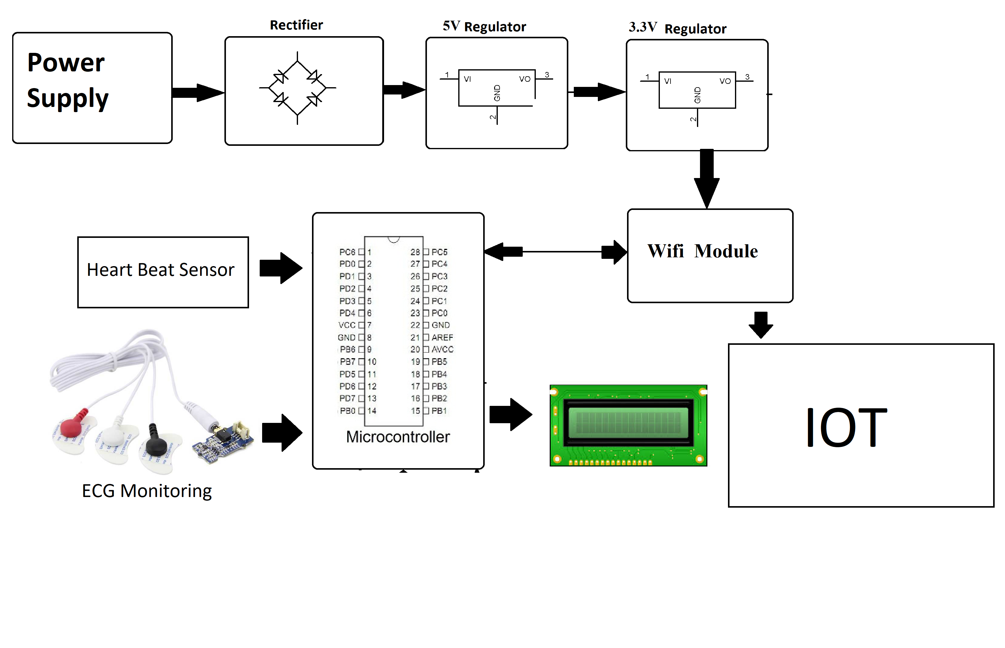
IOT Based Heart Defect Monitoring System Using ECG
Electrocardiography.ppt ECG SIGNAL ACQUISITION HARDWARE DESIGN Origin of Bioelectric Signals Membrane potential membrane composed of a lipid bilayer with embedded proteins Ion transporter/pump proteins actively push ions; ion channels allow ions to move. electrically equivalent to a set of batteries and resistors inserted in the membrane

ECG Basics Heart Blocks Diagnosis Cardiology MedStudent GrepMed
The electrocardiogram (ECG) records from the body surface and registers the differences in electrical potential generated by the heart. The signal recorded is determined by action potentials generated by millions of individual cells and their sequence of activation. A multitude of factors, both cardiac and extracardiac, alter the final electrical signal. For instance, the electrical forces.
Block Diagrams Texas Instruments ECG Electroc... element14 Medical
Figure 2: Block diagram Above is a basic block diagram of our design. It features the main components that we must design to build a functional and portable ECG. Figure 3 below illustrates a criterion for programming capabilities within the structure of the design.

Shows block diagram of a basic single channel ECG machine. The dotted
The ECG demonstrates complete AV dissociation, with independent atrial and ventricular rates. Complete heart block: There is AV dissociation, with the atrial rate (~100 bpm) independent of the ventricular rate (~40 bpm) In complete heart block, there is complete absence of AV conduction, with none of the supraventricular impulses conducted to.